

Scanning-Slit Optical Beam Profilers
- Wavelength Ranges from 200 to 2700 nm
- For Near-Gaussian Beams from Ø2.5 µm to Ø9 mm
- Scanning-Slit and Knife-Edge Operating Modes
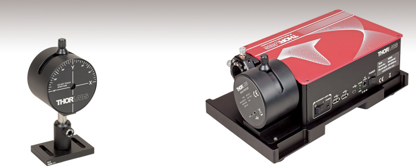
BP209-VIS
Post and Post Holder
Sold Separately
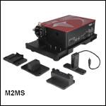
Application Idea
For a complete beam quality measurement system, integrate a beam profiler with an M2 measurement extension set. (Shown: BP209-IR2 and M2MS)
OVERVIEW
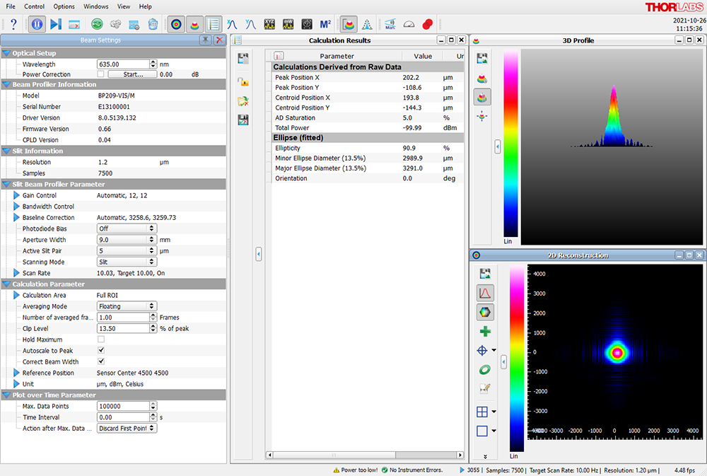
Click to Enlarge
Figure 1.1 One Possible Configuration of the Beam Software GUI Showing Beam Settings, Calculation Results, 2D Reconstruction, and 3D Profile
Features
- Three Dual Scanning Slit Beam Profiler Models
- Item # BP209-VIS(/M) for 200 nm - 1100 nm
- Item # BP209IR1(/M) for 500 nm - 1700 nm
- Item # BP209-IR2(/M) for 900 nm - 2700 nm
- High-Precision Analysis of Near-Gaussian Beam Quality
- Reconstructs 2D and Pseudo 3D Spatial Power Distribution
- Single Stand-Alone Measurement Head
- Characterizes Continuous Wave or ≥10 Hz Pulsed Laser Emission
- Scanning Speeds from 2 to 20 Hz
- User-Calibratable Power Readout (See Manual for User-Calibration Procedure)
- Dynamic Range of 78 dB
- Low-Noise Amplifier
- High-Speed USB 2.0 Interface to PC
- Mounting Adapter Enables Compatibility with a 30 mm Cage System
Thorlabs' Dual Scanning Slit Beam Profilers are ideal for analyzing cross sectional profiles of near-Gaussian laser beams. Measurements of the intensity profiles along the user-specified X and Y axes of the beam's cross section are acquired at scan rates between 2 Hz and 20 Hz, which can be set using the software. The fast 20 Hz scan rate enables real-time optical system alignment. While these beam profilers are primarily intended for CW laser beams, ≥10 Hz pulsed beams can also be measured using an averaging technique (see the Operation tab for more information). These measurements can be used for beam quality evaluation, examination of the reconstructed beam profile, and monitoring long-term stability.
All three Dual Scanning Slit Beam Profiler Models have a Ø9 mm physical input aperture and make measurements by sequentially scanning two slits with the same width and orthogonal orientations across the input laser beam. The software enables users to switch between pairs of 5 µm or 25 µm width slits, select scanning-slit or knife-edge mode operation, and set a range of scan options. For information about the functionality and the usage of the different slit widths and operating modes, please see the Operation tab.
These scanning slit beam profilers are equipped with low-noise electronics, have a high dynamic range of 78 dB, and are capable of measuring beams with diameters between 2.5 µm and 9 mm. The beam diameter is measured in accordance with the ISO 11146 standard and can be displayed using a number of industry-standard clip levels, such as 1/e2 (13.5%), 50%, or an arbitrary clip level set by the user. When the beam of interest does not have a near-Gaussian beam shape, or when single-shot measurements of pulsed beams are required, we recommend our CMOS Camera Beam Profilers.
Thorlabs' Beam software offers complete control over the operation of these beam profilers, providing a broad range of user-adjustable settings as well as display and data logging options. The software can be downloaded from the Software tab and installed on a user-supplied PC. When the beam profiler is connected to a PC running the Beam software, no additional hardware or power supply is required. Thorlabs utilizes a high-speed USB 2.0 interface to connect the measurement head with the PC, and the required USB cable is included with the BP209 package. Flexible data export options as well as a data interface for National Instruments® software ease the integration of these profilers into customized data processing environments. Information about installing drivers, file locations, and reference notes for interfacing with our beam profilers using LabVIEW™, C, Visual C#, and Python are available in the user manual, which can be found by clicking on the red Docs icon (![]() ) next to the item number. Please see the User Interface tab or the user manual for more details on the functionality of the software.
) next to the item number. Please see the User Interface tab or the user manual for more details on the functionality of the software.
To mount a scanning slit optical beam profiler in a 30 mm cage system, the BPS209CSA(/M) mounting adapter (available below) can be used. Four Ø6 mm bores provide compatibiltiy with our Ø6 mm cage rods (not included).
M2 Measurement Systems
A complete M2 measurement system based on a BP209 beam profiler can be built by integrating the profiler with a wavelength-compatible extension set, available below. Information about all of Thorlabs' M2 measurement systems, as well as the option to configure and purchase a system with the BP209 beam profiler of your choice, can be found on the
SPECS
| Item # | BP209-VIS | BP209-VIS/M | BP209IR1 | BP209IR1/M | BP209-IR2 | BP209-IR2/M |
|---|---|---|---|---|---|---|
| Beam Profiler Specifications | ||||||
| Wavelength Range | 200 - 1100 nm | 500 - 1700 nm | 900 - 2700 nm | |||
| Detector Material | UV-Enhanced Si | InGaAs | Extended InGaAs | |||
| Aperture Diameter | 9 mm | |||||
| Scan Methods | Scanning Slits, Knife Edge | |||||
| Slit Size | 5 µm and 25 µm | |||||
| Minimum Beam Diameter | 2.5 µm | |||||
| Maximum Beam Diameter | 9 mma | |||||
| Scan Rate | 2.0 - 20.0 Hz (Continuously Variable) | |||||
| Sampling Resolution | 0.12 - 1.24 µm (Depending on Scan Rate) | |||||
| Power Range | 1 µW - 10 W (Depending on Beam Diameter and Model; See Figure 2.2) | |||||
| Amplifier Bandwidth | 16 to 1000 kHz in 11 Steps (@ -1 dB) | |||||
| Sample Frequency | 0.2872 - 2.0 MHz | |||||
| Dynamic Range | 78 dB (Amplifier Switchable) | |||||
| PD Reverse Bias Voltage | 0 / -1.5 V (Switchable) | 0 V | ||||
| Signal Digitization | 15 Bit | |||||
| Dimensionsb | Ø79.5 mm x 60.0 mm (Ø3.13" x 2.36") Including Rotation Mount | |||||
| Minimum Pulse Rate | 10 Hzc | |||||
| Warm-Up Time for Rated Accuracy | 15 min | |||||
| Software | ||||||
| Displayed Parameters/Features | X-Y-Profile, Centroid Position, Peak Position, Pseudo 3D Profile, Beam Width Clip Level/Second Moment (4σ), Gaussian Fit Applicable, Pass/Fail Test with Color-Coded Results |
|||||
| Compliant to Norm | ISO 11146 (Beam Widths, Divergence Angle and Beam Propagation Factor) | |||||
| Minimum System Requirements | Windows® 8.1 or Later, USB 2.0 High Speed Port, 4.0 GB RAM | |||||
| M² Analysis System (M2 Extension Set Available Separately) | ||||||
| Compatible M² Extension Set(s)d | M2MS or M2MS-AL | M2MS | ||||
| Compliant to Norm | ISO 11146 | |||||
| Measured Parameterse | M², Waist Width, Waist Position, Rayleigh Length, Divergence, Beam Pointing, Waist Asymmetry, Astigmatism | |||||
| Environmental | ||||||
| Operating Temperature | 5 °C to 35 °C | |||||
| Storage Temperature | -40 °C to 70 °C | |||||
All technical data are valid at 23 °C ± 5 °C and 45 ± 15% relative humidity.
Click to Enlarge
Figure 2.2 These maximum and minimum beam power limits are provided as functions of 1/e2 beam diameter for knife-edge and scanning-slit measurements and may not apply to measurements of total power. Please see the Operation tab for more information. To prevent thermal damage to the measurement head, do not operate for longer than 5 s with input powers exceeding 1 W.

Click to Enlarge
Figure 2.1 Click here for an Excel file containing these measured responsivity data.
Slit and Photodiode Position
Accurate measurements require a ≤Ø9 mm beam to be centered in the entrance aperture, the slits to scan the entire beam, and all transmitted power to be incident on the photosensitive surface of the photodetector. Figures 2.3 and 2.4 show the distances of the slit location and the position of the photosensitive surface of the photodiode from the front face of the entrance aperture. These dimensions are provided to help the user ensure that the optical input, especially in the case of a highly diverent beam, is not clipped by the entrance pupil and does not overfill the photosensitive surface of the photodetector.

Click to Enlarge
Figure 2.4 BP209IR1(/M) and BP209-IR2(/M) Mechanical Drawing
OPERATION
Click to Enlarge
Figure 3.1 An example of operation in Knife-Edge Mode, when the beam diameter is less than the slit width, is shown here.
Scanning-Slit and Knife-Edge Techniques
The BP209 series of Scanning Slit Beam Profilers analyze near-Gaussian, elliptical (or circular) free-space optical beams using either the scanning-slit or the knife-edge technique, depending on the diameter of the beam. These approaches scan two slits, one after the other, across the full cross section of the beam. One slit is scanned along the X axis of the beam, and the other slit is scanned along the Y axis, where the X and Y axes are defined by the user and frequently correspond to the major and minor axes of the ellipse. The light transmitted by the slit is incident on a photodetector. Optical intensity measurements, which are referenced to the position of the slit, are acquired as the slit scans across the beam.
The scanning-slit mode is appropriate for beams whose diameters are at least four times the width of the slits. In this mode, when the beam overlaps with the slit, a sliver of the beam with a width equal to that of the slit is transmitted. As the slit scans across the beam, the optical intensity of the sampled beam segments is measured by the photodetector. Knife-edge mode should be used when the beam diameter is smaller than the slit width. In knife-edge mode, the scanning slit transmits fractions of the beam, from zero to 100%. The scanning slit first overlaps with and transmits little of, then more of, and eventually all of the beam. The amount of overlap between the slit and the beam, and therefore the transmitted optical intensity, decreases and becomes zero again as the slit continues to scan across the beam.
These measurements are used to determine the beam intensity profiles along the X and Y axes of the beam. Using these data, peak power and beam centroid locations with respect to each axis are found, as well as beam diameter and ellipticity. By assuming the beam has a near-Gaussian profile, the measured X and Y beam profiles can also be used to reconstruct the intensity profile of the full beam cross section and plot the results in either 2D or 3D formats.
Operational Overview of the BP209 Series Beam Profilers
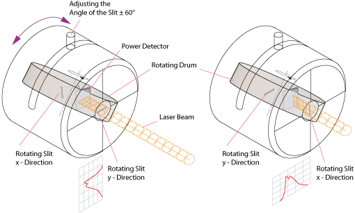
Figure 3.2 Internal to the BP209 series measurement heads is a rotating drum, whose axis of rotation is adjusted using a manual knob. Slits in the drum are scanned across the X and the Y axes of the beam as the drum rotates, and transmitted intensity is detected by an integrated photodetector.
Click to Enlarge
Figure 3.3 These maximum and minimum beam power limits are provided as functions of 1/e2 beam diameter for knife-edge and scanning-slit measurements and may not apply to measurements of total power. To prevent thermal damage to the measurement head, do not operate for longer than 5 s with input powers exceeding 1 W.
Thorlabs' Beam Software
Thorlabs' Beam software, which was developed to control and acquire measurements using our beam profilers and related M2 measurement systems, can be downloaded from the Software tab. The software includes a GUI and enables detailed control over the scan and measurement settings, including selecting the active slit pair, scanning mode, gain, averaging mode, and scan rate. The configuration and appearance of the displayed windows, which include X Profile, Y Profile, 2D Reconstruction, 3D Profile, Position vs. Time, Power vs. Time, and Calculation Results, can be adjusted as desired. The software enables M2 beam quality and convergence/divergence measurements to be made and also includes tools to assist with the task of overlapping two different laser beams. The user can select which measurement and calculation results to save to a file, and data accquired during long-term measurements can be sequentially saved. For an introduction to the software and representative screenshots, please see the User Interface tab. For detailed information describing the software's functionality, please see the manual.
Perform Measurements with 5 µm or 25 µm Slits
Figure 3.2 illustrates the configuration of the measurement head, which includes an input aperture and a rotating drum with slits in it. The beam enters the Ø9 mm input aperture perpendicular to the front plane of the measurement head and is incident on the rotating drum. The slits in the drum are spaced at intervals, and each slit spans the full width of the input aperture. There are two pairs of slits in the drum, and each pair includes one oriented at +45° with respect to the axis of rotation and the other oriented at -45°. Both slits in one pair are 5 µm wide, while those in the other pair are 25 µm wide. Including two slit width options in each measurement head and offering two operating modes enables beams with an extended range of diameters and powers to be profiled.
If the beam diameter is equal to or less than 20 µm, use the 25 µm slits and operate in Knife-Edge mode. Beams with diameters as small as 2.5 µm can be measured using this approach.
The Scanning-Slit mode can be used to measure beams with diameters between 20 µm and 9 mm. As a general rule, choose slits with widths at least four times smaller than the beam diameter to make the measurement. When this condition is met by both slit widths, the choice of scanning slit pair is influenced by the beam power and application requirements.
Measure Beams with a Wide Range of Powers
The maximum and minimum beam powers accommodated by the scanning-slit beam profilers are shown as function of the 1/e2 beam diameter in Figure 3.3. The vertical black line at 20 µm marks the beam diameter at which it is necessary to switch between knife-edge and scanning-slit operating modes. In scanning-slit mode, the maximum beam power limits correspond to operation with the 5 µm slits. By transmitting a smaller portion of the beam than the 25 µm slits, using the 5 µm slits allows beams with higher power to be measured. The minimum beam power limits were determined in scanning-slit mode using the 5 µm slits for beams with diameters between approximately 20 µm and 100 µm, while the 25 µm slits were used for beams with larger diameters. Switching between the slits when the beam diameter exceeds 100 µm maximizes the amount of beam power reaching the photodetector while also maintaining an adequate ratio between slit width and beam size.
As discussed below, reduced maximum and/or increased minimum beam power limits may apply when the beam profiler is used to measure total power (see below). If the Total Power measurement falls outside of the applicable limits, an error message will be displayed in the status box in the software GUI. However, beam shape measurements using the slits can still be made, assuming the power transmitted by the slits falls within the limits plotted in Figure 3.3.
Acquire Total Power Measurements (Power Meter Readings)
In addition to the two pairs of slits, the rotating drum contains an aperture fitted with a neutral density (ND) filter. Once per rotation, the full beam passes through this aperture, and its attenuated total intensity is measured by the photodetector. This Total Power measurement is used as a reference value for the beam profile measurements, and it can also be measured and plotted with respect to time in a GUI window. The Total Power measurement is corrected using the typical wavelength-dependent responsivity, but it is not a calibrated value. To obtain absolute optical power measurements, the user can use the software to record a calibration measurement at the wavelength of interest.
The ranges of maximum and minimum beam powers for which Total Power measurements can be acquired may not reach the limits plotted in Figure 3.3. The limits in the graph were determined for knife-edge and scanning-slit mode operation. Scanning-slit mode transmits a fraction of the beam power to the photodetector, and during knife-edge mode the un-attenuated, ≤Ø20 µm, full beam is transmitted to the photodetector. The power in the attenuated full beam that reaches the photodetector during Total Power measurements may need to fall within reduced maximum and/or increased minimum limits than the beam powers accommodated when operating with the slits.
Click to Enlarge
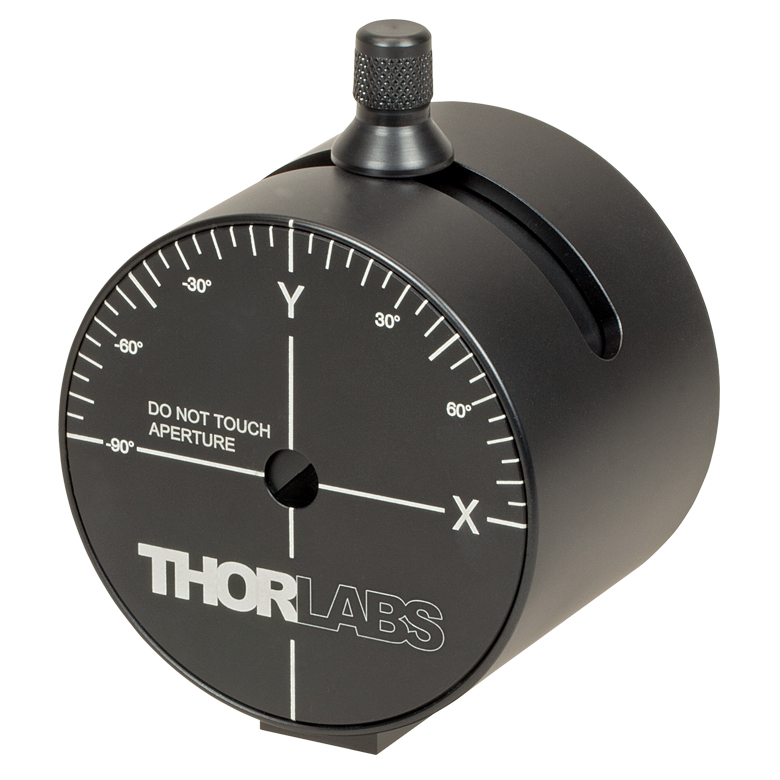
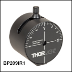
Figure 3.4 The laser-engravings on the front face show the orientation of the X and Y axes when the knob is vertical and can be used to estimate the axes' orientation when the knob is rotated.
Choose the X and Y Scan Axes' Orientation
The knob at the top of the measurement head, which is shown in Figure 3.4, is used to manually adjust the drum’s axis of rotation by ±60°. Adjusting the drum’s axis of rotation changes the orientation of the X and Y scan axes with respect to the beam cross section. This allows the beam profile to be measured with the scan axes defined as desired, and it enables a series of measurements to be acquired in which the orientation of the scan axes are different in each. The drum is located internally to the measurement head, and rotating the knob does not rotate the measurement head.
This functionality is of particular importance when the input beam has an elliptical cross section, as the scan axes must be aligned with the major and minor axes of a given beam in order to measure the real ellipticity. To achieve the most accurate alignment for an ellipticity measurement, rotate the knob while observing the X and Y intensity profiles plotted in the software. When the profile width in one axis is a minimum and the other is a maximum, the rotation angle is optimal.
Measure the Beam Profile of Pulsed Laser Beams
The BP209 series can be used to measure the beam profiles of pulsed laser beams with repetition rates greater than or equal to 10 Hz; however, Thorlabs' camera beam profilers are a better choice for applications that require single-shot measurements.
There is no difference between analyzing a CW signal and a pulsed signal when the pulse repetition rate is high and the duration is short, as is the case with a femtosecond laser with 100 MHz repetition rates and pulse durations lower than 100 fs. This is due to the limited bandwidth of the photodiode’s current amplifier, which cannot resolve the individual pulses and instead effectively averages the input pulse train to produce a CW signal.
When pulse rates are lower, on the order of 50 kHz or less, configure the Scan Rate setting in the software to achieve optimal measurements. As the scan rate can be set between 1.5 Hz and 20 Hz, it is frequently not possible to set the scan rate to be as fast as the pulse rate. Set the scan rate so that an integer multiple of the scan rate is slightly different than the pulse rate. Then, perform the measurement with the Hold Maximum function enabled. A set of scans are performed, and the software accumulates and averages the measured peak intensities in the scan set. When the pulse rate is fast enough for more than one pulse to be measured during a single scan, the software will accumulate and average the peak intensities of all the measured pulse segments. The reported beam profile is the final average of the set of measurements. Setting the integer multiple of the scan rate to differ slightly from the pulse rate ensures that each scan measures a different portion of the beam profile; the set of scans should include measurements of all segments of the beam profile.
USER INTERFACE
Main Window

Click to Enlarge
Figure 4.1 The main window of the GUI includes the menu bar, tool bar, status bar, and a frame where several windows can be displayed. This screenshot shows several panels: Beam Settings, Calculation Results, 2D Reconstruction, and 3D Profile. The Beam Settings Panel displays all important information in a single location; this panel can be unpinned from the main window and moved to a second location, such as another monitor.
Thorlabs Beam Software for the BP209 Beam Profilers
- GUI with Adjustable Layout: Windows with Different Measurement Results
can be Rearranged and Resized within the Workspace - 2D and 3D Views of the Beam Profile
- Selectable Overlays such as Peak, Centroid, and Cut Profiles
- 3D View is Fully Rotatable
- M² and Divergence Measurements Compliant with ISO 11146
- Data Export:
- Results can be Exported from Windows in Different Formats
- Sequential Saving of Long Term Test Data
- Pass/Fail Tests with Customizable, Lockable and Saveable Pass/Fail Parameters
- Power Correction Available for Absolute Power Measurements
- Supports TSP01 for Temperature Logging During Long-Term Measurements
Thorlabs' Scanning Slit Beam Profilers, Camera Beam Profilers, and M² Measurement Systems all use the Thorlabs Beam software package. The screenshots below highlight key features and measurement modes that can be used with our scanning slit beam profilers, including 2D reconstructions of the beam profile and measurements of the beam stability and position. If an M² Extension Set (available below) is added to the system, the software also enables M² and beam divergence measurements.
The latest version of the Beam software package can be downloaded from the Software tab.
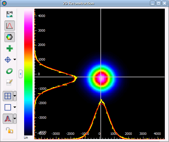
2D Reconstruction of the Beam Profile
Click to Enlarge
Figure 4.2 Slit beam profilers only measure two real orthogonal cross sections of the beam (i.e., the beam profile in X and Y). Assuming a Gaussian-like beam profile, the Beam software package can create a 2D reconstruction of the beam profile from the two cross sections, seen in the screenshot above. Buttons along the side allow users to save the image, show or hide the x and y scales, mark the centroid or peak position, and display an approximated Beam Ellipse superimposed on the image.
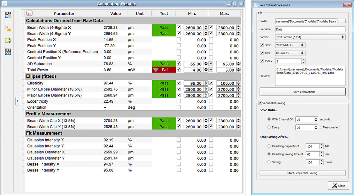
Calculation Results
Beam Stability

Click to Enlarge
Figure 4.4 The Beam Stability Window allows the stability versus time to be recorded and viewed. Display options include the Centroid Positions, Latest Plotted Centroid, Rolling Centroid Positions, Reference Positions, and Smallest Enclosing Circle.
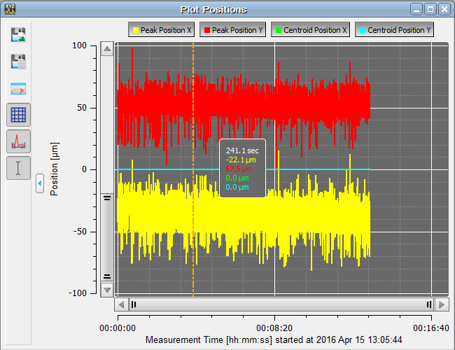
Plot Centroid and Peak Positions
Click to Enlarge
Figure 4.5 The positions of the X and Y peak and X and Y centroid positions can be displayed as a function of time in this window.
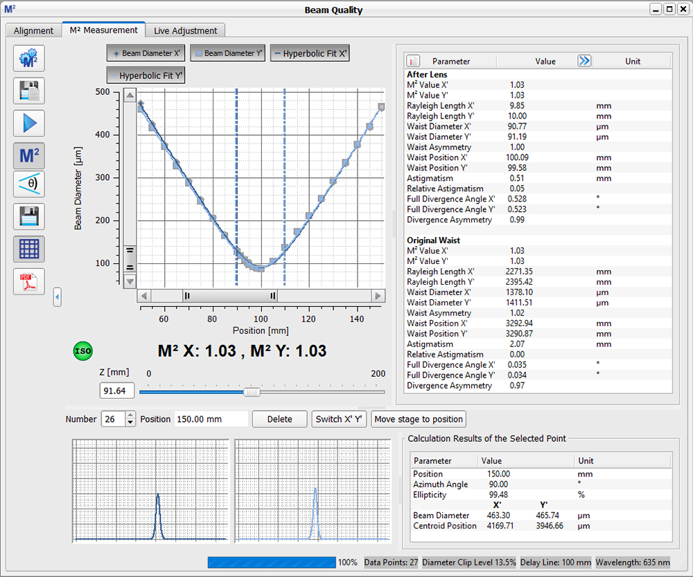
M2 Measurements
Click to Enlarge
Figure 4.6 The beam diameter and location of the beam waist are shown after an M² analysis has been performed. Note: This functionality is only enabled when using a beam profiler with one of the M² systems.
Convergence / Divergence Measurements
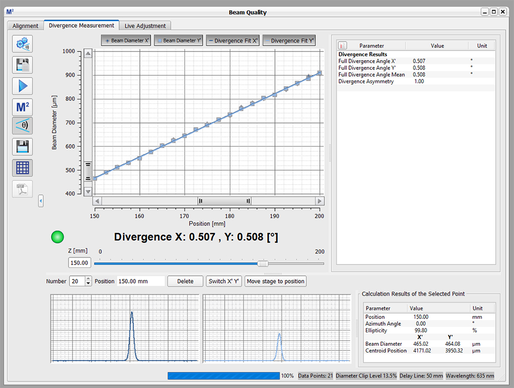
Click to Enlarge
Figure 4.7 The divergence of the beam is shown after an M² analysis has been performed. Note: This functionality is only enabled when using a beam profiler with one of the M² systems.
SOFTWARE
Software Packages for Thorlabs' Beam Profilers
The Beam software package can be downloaded by clicking on the Software button here. Please refer to the manual's programming references for interfacing with our beam profilers using LabVIEW™, C, Visual C#, and Python.
| System Requirements | ||
|---|---|---|
| Operating System | Windows® 8.1 (32 Bit or 64 Bit), 10 (32 Bit or 64 Bit), or 11 (for Beam Version 9.0 or Higher) |
|
| Connectivity | Scanning-Slit | USB 2.0 High Speed Port |
| Camera | USB 3.0 High Speed Port | |
| Monitor Resolution | 1024 x 758 Pixel (Min), ≥16 Bit Color Depth | |
| Processor (CPU) | Minimum | ≥3.0 GHz Intel Core (i5 or Higher)a |
| Recommended | Intel Core 2 i5 or AMD Ryzen 5 (3.0 GHz Min) | |
| Memory (RAM) | Minimum | 4.0 GB RAM |
| Recommended | 8.0 GB RAM | |
| Graphics Adapter | Required | OpenGL (Specification GLX 1.3 Up) |
| Minimum | Radeon: X100 Series ≥X850, X1000 Series ≥X1600, HD Series ≥2400; Geforce: 7 Series ≥7600, 8 Series ≥ 8500, 9 Series ≥9600; Quadro: FX Series ≥FX770M |
|
| Recommended | Radeon: HD Series ≥7000; Geforce: GTX Series ≥500; |
|
| Hard Drive | Minimum | 2 GB of Available Disk Space |
Features
- Settings Panel Displays All Important Parameters in a Central Location
- Customizable Calculation Results
- Measured Parameters can be Individually Hidden
- Adjustable Row Heights
- Enhanced Beam Stability Window Measures and Displays the
Smallest Enclosing Circle Around the Centroid Point Cloud
- Alignment Wizard to Aid in Correctly Aligning the M2MS M2 Measurement Systems
- Language Settings of English, German, or Chinese
Software
Version 9.2.6002.614 (February 12, 2025)
Standard full version of software package for 32-bit and 64-bit Windows with driver and graphical user interface for operating the device in standard applications.

Firmware Update for Scanning Slit Beam Profilers
Here is a link to a firmware update for Thorlabs scanning slit beam profilers to correct an error regarding hardware and firmware compatibility.
Firmware Update
Version 1.6 (April 26, 2024)
Click on the link below to download the latest firmware. The link includes instructions for installing the firmware update.

SHIPPING LIST
Each Beam Profiler Comes with the Following Parts:
- BP209 Series Beam Profiler Head with Dust Cover
- High-Speed USB 2.0 A to Mini-B Connection Cable, 3.0 m
- Quick Start Guide
Scanning Slit Optical Beam Profilers
| Key Specifications | ||||||
|---|---|---|---|---|---|---|
| Item #a | ||||||
| Wavelength Range | 200 - 1100 nm | 500 - 1700 nm | 900 - 2700 nm | |||
| Detector Material | UV-Enhanced Si | InGaAs | Extended InGaAs | |||
| Aperture Diameter | 9 mm | |||||
| Scan Methods | Scanning Slits, Knife Edge | |||||
| Slit Sizes | 5 µm and 25 µm | |||||
| 2.5 µm - 9 mm | ||||||
Part Number | Description | Price | Availability |
|---|---|---|---|
BP209-VIS/M | Dual Scanning Slit Beam Profiler, 200 - 1100 nm, Ø2.5 µm - Ø9 mm, Metric | $5,264.81 | Today |
BP209IR1/M | Customer Inspired! Dual Scanning Slit Beam Profiler, 500 - 1700 nm, Ø2.5 µm - Ø9 mm, Metric | $5,978.53 | Lead Time |
BP209-IR2/M | Dual Scanning Slit Beam Profiler, 900 - 2700 nm, Ø2.5 µm - Ø9 mm, Metric | $8,100.00 | Today |
BP209-VIS | Dual Scanning Slit Beam Profiler, 200 - 1100 nm, Ø2.5 µm - Ø9 mm, Imperial | $5,264.81 | Today |
BP209IR1 | Customer Inspired! Dual Scanning Slit Beam Profiler, 500 - 1700 nm, Ø2.5 µm - Ø9 mm, Imperial | $5,978.53 | Today |
BP209-IR2 | Dual Scanning Slit Beam Profiler, 900 - 2700 nm, Ø2.5 µm - Ø9 mm, Imperial | $8,100.00 | Today |
M² Measurement Extension Sets
| Item # | M2MS-AL | M2MS | |
|---|---|---|---|
| Wavelength Range | 250 - 600 nma | 400 - 2700 nma | |
| Beam Profiler Compatibilityb | BC207UV(/M)c BP209-VIS(/M) BC210CU(/M)c |
BC207VIS(/M)d BP209-VIS(/M) BP209IR1(/M) BP209-IR2(/M) BC210CV(/M)d |
|
| Internal Translation Stage | Travel Range | 100 mm | |
| Velocity (Max) | 500 mm/s | ||
| Effective Translation Range | 200 mm (Total) ±100 mm (from Focal Point) |
||
| Lens Focal Length | 250 mm | ||
| Optical Axis Height | 70 mm (Without Additional Feet) |
||
| M² Measurement Range | ≥1.0 (No Upper Limit) | ||
| Typical M² Accuracy | ±5% (Depends on Optics and Alignment) |
||
| Minimum Detectable Divergence Angle | <0.1 mrad | ||
| Applicable Light Sources | CW, Pulseda | ||
| Typical Measurement Time | 15 - 30 s |
||
| General Specifications | |||
| Size | 300 mm x 175 mm x 109 mm (Without Beam Profiler) |
||
| Weight | 4.2 kg (Without Beam Profiler) |
||
- Combine with BP209 Scanning Slit Beam Profilers to Build
Complete M2 Measurement System - Mirrors for the 250 - 600 nm or 400 - 2700 nm Range
- Mounting Adapters for BC207 and BC210C* Series Camera Beam Profilers and BP209 Series Scanning Slit Beam Profilers
- Includes an Alignment Laser
These extension sets are designed to convert Thorlabs' Camera or Scanning Slit Beam Profilers into a fully automated, motorized M² measurement system. The
The beam profiler and focusing lens remain in a fixed position. For M2 measurements, the beam path length is varied using a movable retroreflector mounted on a translation stage, which has a translation range of 200 mm and a maximum velocity of 500 mm/s.
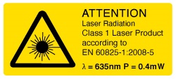 Figure G2.1 Each extension kit ships with a Class 1 alignment laser.
The side of the M² measurement system features an integrated USB 2.0 hub, which has ports for the slit beam profiler, one other device such as the TSP01 USB temperature and humidity controller, and a mini USB output connection to a PC. The translation stage inside of the system also communicates with the computer through this hub. As the BC207 and BC210C series beam profilers use USB 3.0 ports, they should be connected directly to a PC using their included USB 3.0 cables when used with the M2MS(-AL) system. The M2 measurement system extension set is controlled via the Thorlabs Beam software package, which is also use to control our beam profilers (see the Software tab) and enables accurate measurements of a variety of beam-related parameters.
The housing of the M2 measurement rests on four feet at the corners created by a 0.5 mm deep relief cut in the base. A set of RDF1 rubber damping feet are included. Five M6 taps allow for the installion of four damping feet with one near each corner or in a configuration using three damping feet.
More information about these complete M² measurement systems can be found here.
*Users who purchased an M2 measurement system extension set before August 8, 2023 and wish to use a BC210C Series Camera Beam Profiler may receive the appropriate adapter by contacting Tech Sales.
Accessories Included with M2MS-AL and M2MS
- Alignment Laser
- USB 2.0 to Mini B Cable, 3 m
- USB 2.0 to Mini B (Angled), 0.5 m
- 15 V, 3.0 A Power Supply
- 0.05" Hex Key
- 3 mm Balldriver
- 4 Rail Clamps
- 6 M4 Cap Screws
Part Number | Description | Price | Availability |
|---|---|---|---|
M2MS-AL | M² Measurement System Extension Set, 250 - 600 nm | $7,295.97 | Lead Time |
M2MS | M² Measurement System Extension Set, 400 - 2700 nm | $7,295.97 | Today |
Scanning Slit Optical Beam Profiler to 30 mm Cage Adapter
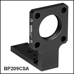
- Adapts the BP209 Series Scanning Slit Beam Profilers to a 30 mm Cage System
- SM1 (1.035"-40) Threaded Bore
The BP209CSA(/M) Adapter can connect a Thorlabs' BP209 Series Scanning Slit Beam Profiler to a 30 mm cage system. An SM1 (1.035"-40) threaded bore in the adapter allows for compatibility with our Ø1" lens tubes or a Ø1" optic up to 3.6 mm (0.14") thick, when secured with a SM1RR retaining ring (not included). Four blind holes with 5/64" (2.0 mm) hex locking setscrews accept Ø6.0 mm cage rods (not included).
To mount the BP209CSA(/M) to a scanning slit beam profiler, first rotate the Y scan axis of the beam profiler to +60° or -60°, then turn the unit upside down, allowing access to the bottom mounting plate. Use the 2.0 mm (5/64") hex key included with the BP209CSA(/M) adapter to remove the four 5 mm long, M3 x 0.5 hex socket head screws*. Fully remove the bottom plate on the beam profiler, and mount the BP209CSA(/M) adapter in its place using the screws removed from the beam profiler.
*For BP209 Series Dual Scanning Slit Beam Profilers made prior to July 2022, the bottom plate is secured via four 5 mm long, M3 x 0.5 Phillips head screws. A #1 Phillips screwdriver (not included) is required to remove these screws.
Part Number | Description | Price | Availability |
|---|---|---|---|
BP209CSA/M | Customer Inspired! BP209 Series Beam Profiler to 30 mm Cage System Adapter, M4 and M6 Mounting Holes | $160.50 | Today |
BP209CSA | Customer Inspired! BP209 Series Beam Profiler to 30 mm Cage System Adapter, 8-32 and 1/4"-20 Mounting Holes | $160.50 | Today |