

Single Photon Detectors
- Single Photon Detection or Counting Modules
- Low Max Dark Counts: 60 Hz - 1500 Hz
- Detector Sizes of Ø20, Ø50, Ø100, or Ø500 µm
- Active Quenching and Temperature Stabilization
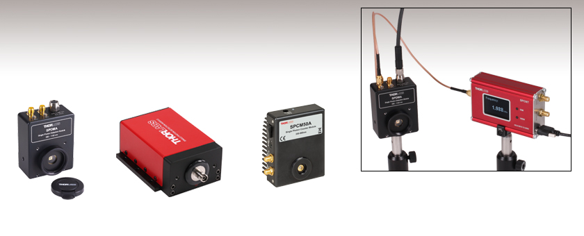
SPCM50A
Single Photon Counting Module
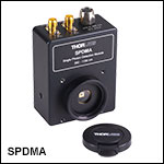
SPDMA
Single Photon Detection Module with Adjustable Gain
SPDMH2F
Single Photon Detection Module with Fixed Gain, FC/PC Connector
Application Idea
Single Photon Counting Device Counts Pulses from the SPDMA Detection Module
OVERVIEW
Click to Enlarge
Figure 1.1 The Photon Detection Efficiency (PDE) is shown here as a function of wavelength for the SPDMA module at both Max and Min Gain, the SPDMHx modules, and the SPCMxxA(/M) modules. The operating range of the SPDMA module is 350 nm - 1100 nm, for the SPDMHx modules it is 400 nm - 1000 nm, and the operating range of the SPCMxxA(/M) modules is 350 nm - 900 nm.
Applications
- Spectroscopy with Single Molecules
- Spectro-Photometrical Measurements
- Flow Cytometry
- Photon Correlation Spectroscopy
- Quantum Optics
- LIDAR
Features
- Single Photon Detection or Counting Modules
- Visible and NIR Wavelength Responsivity
- Low Max Dark Count Rates: 60 Hz - 1500 Hz
- Four Detector Sizes: Ø20 µm, Ø50 µm, Ø100 µm, or Ø500 µm
- Active Quenching
- Temperature Stabilization
- Pulse Output
- TTL Gating/Trigger Input
- Single Photon Counting Device for use with Detection Modules
Thorlabs offers single photon detectors and counting modules with a range of photon detection efficiencies (PDEs), detector sizes, gain options, and wavelength ranges. The SPDMA Single Photon Detection Module, designed for use from 350 to 1100 nm, features continuously adjustable gain and an SMA electrical connector from which the TTL output can monitored by an oscilloscope or external counter. Comparatively, the SPDMHx Fixed-Gain Single Photon Detection Modules, for use from 400 to 1000 nm, combine a higher PDE in the NIR (see Figure 1.1) with low maximum dark count rates; the output TTL pulses are accessible via a LEMO connector.
The SPCNT Single Photon Counting Device can be used in conjunction with either the SPDMA detector or SPDMHx series of detectors to provide a full detection and counting solution. The counting device recognizes signal pulses originating from a connected single photon detector and shows the results numerically as counts or frequency on the built in display, or on a connected PC for display and analysis. The device can be controlled by the Optical Parameter Monitor (OPM) software when connected to a PC, see the Software tab for details.
Finally, the SPCMxxA(/M) Single Photon Counting Modules have an internal 31-bit photon counter, include a software package for controlling the detector and reading the output, and are intended for use from 350 to 900 nm. A comparison of the PDEs of the detectors is shown in Figure 1.1.
Each single-photon detector or module uses a silicon avalanche photodiode (see the Tutorial tab for a description of the operating principle). The active quenching circuit integrated into the diode of these single photon detection systems enables high count rates, allowing users to detect a photon every 35 ns - 45 ns, depending on the model chosen. The diodes are actively temperature stabilized to achieve low maximum dark count rates of 60 Hz - 1500 Hz, depending on the model and settings, with power level detection down to fW. Please see the Specs tab for complete specifications on all modules.
For detectors that offer an array of silicon avalanche photodiodes for low light and single photon detection, Thorlabs offers a series of silicon photomultipliers as well.
Software for SPCMxxA(/M) Counting Modules
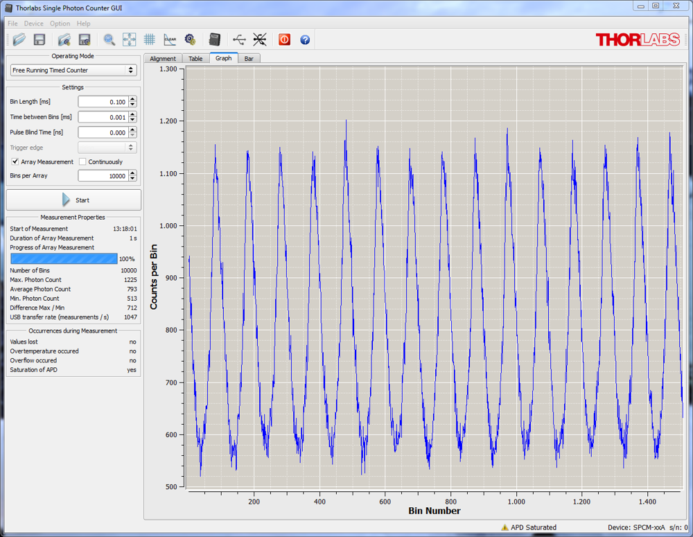
The Single Photon Counter Modules include a software package with GUI for out-of-the-box operation. The following operating modes can be set by the software:
- Manual Mode for manual operation, where the counter is started and stopped manually by pressing the Start/Stop button (toggle function).
- Free Running Timer Counter for counting incident photons for a certain number of "Time Bin Lengths."
- Externally Triggered Timer Counter for triggering the timer start for counting incident photons for a certain time period.
- Externally Triggered Counter for starting and stopping the counter by an external trigger.
- External Gating for activating the counter and the APD externally.
For more details about the software and its operation modes, please see the Software tab.
| Detector Key Specificationsa | |||||||
|---|---|---|---|---|---|---|---|
| Item # | SPDMA | SPDMH2 | SPDMH2F | SPDMH3 | SPDMH3F | SPCM20A(/M) | SPCM50A |
| Type | Single Photon Detection Module | Single Photon Detection Module | Single Photon Counting Module | ||||
| Wavelength Range | 350 - 1100 nm | 400 - 1000 nm | 350 - 900 nm | ||||
| Dark Count Rate | @ Min Gain: <75 Hz (Typical); <400 Hz (Max) @ Max Gain: <300 Hz (Typical); <1500 Hz (Max) |
100 Hz (Max) | 250 Hz (Max) | 25 Hz (Typical) 60 Hz (Max) |
150 Hz (Typical) 200 Hz (Max) |
||
| Active Detector Size | Ø500 µm | Ø100 µmb (Nominal) | Ø20 µm | Ø50 µm | |||
| Connector Style | Free Space | Free Space | FC/PC | Free Space | FC/PC | Free Space | Free Space |
| Software | No | No | Yes | ||||
| SPCNT Device Compatible | Yes | No | |||||
SPECS
| Table 2.1 Specifications | |||||||
|---|---|---|---|---|---|---|---|
| Item # | SPDMA | SPDMH2 | SPDMH2F | SPDMH3 | SPDMH3F | SPCM20A(/M) | SPCM50A |
| Detector | |||||||
| Detector Type | Si Avalanche Photodetector | ||||||
| Wavelength Range | 350 nm - 1100 nm | 400 nm - 1000 nm | 350 nm - 900 nm | ||||
| Active Detector Size | Ø500 µm | Ø100 µma (Nominal) | Ø20 µm | Ø50 µm | |||
| Gain Adjustment Factor (Typical) | 4 | N/A | N/A | ||||
| Typical Photon Dectection Efficiency | @ Max Gain 58% @ 500 nm 66% @ 650 nm 43% @ 820 nm |
10% @ 405 nmb 50% @ 520 nmb 70% @ 670 nmb 60% @ 810 nmb |
35% @ 500 nm | ||||
| PDE Variation at Constant Temperature (Typical) | N/A | ~1% | ~5% | ~1% | ~5% | N/A | |
| Dark Count Rate | @ Min Gain: <75 Hz (Typical); <400 Hz (Max) @ Max Gain: <300 Hz (Typical); <1500 Hz (Max) |
100 Hz (Max) | 250 Hz (Max) | 25 Hz (Typical); 60 Hz (Max) |
150 Hz (Typical); 200 Hz (Max) |
||
| Count Rate | @ Max Gain: 20 MHz (Typical); >10 MHz (Min) |
20 MHz (Max) | 28 MHz (Max) | 22 MHz (Max) | |||
| Timing Resolution (Typical) | N/A | 1000 ps | N/A | ||||
| Dead Time | <35 ns (@ Max Gain) | 45 ns (Typical) | 35 ns (Typical) | 45 ns (Typical) | |||
| APD Gating Delayc | N/A | N/A | 18 ns (Typical) | ||||
| Gate / Trigger In to Pulse Out Delayd | N/A | N/A | 28 ns (Typical) | ||||
| Delay Between Photon Impact and TTL Pulse (Typical) |
N/A | 30 ns | N/A | ||||
| Afterpulse Probability | 1% (Typical @ Min Gain) | 0.2% (Typical) | 3% | ||||
| APD Temperature Stability | <0.01 K | N/A | <0.1 K | ||||
| Trigger Input TTL Signal Low (Closed) High (Open) |
<0.8 Ve >2 Ve |
0.5 Vf 2.4 Vf |
<0.8 V >2 V |
||||
| Trigger Input Response Time Closing Signal Opening Signal |
N/A N/A |
15 ns (Typ) to 20 ns (Max) 60 ns (Typ) to 65 ns (Max) |
N/A N/A |
||||
| Output Pulse Width @ 50 Ω Load | 10 ns (Min); 15 ns (Typ); 20 ns (Max) |
15 ns (Typ); 17 ns (Max) | N/A | ||||
| Output Pulse Amplitude @ 50 Ω Load TTL High TTL Low |
3.5 V 0 V |
3 V (Typical) N/A |
3.5 V 0 V |
||||
| SPCNT Counting Device Compatible | Yes | No | |||||
| Input Fiber Compatibility | |||||||
| Fiber Connector | N/A | N/A | FC/PC | N/A | FC/PC | N/A | |
| Input Fiber Core Diameter (Max) | N/A | N/A | <105 μm | N/A | <105 μm | N/A | |
| Numerical Aperture (NA) | N/A | N/A | ≤0.29 | N/A | ≤0.29 | N/A | |
| General | |||||||
| Dimensions (W x H x D) | 72.0 x 51.3 x 27.4 mm (2.83'' x 2.02'' x 1.08'') |
105.6 x 40.1 x 76.0 mm (4.16'' x 1.58'' x 2.99'') |
116.0 x 40.1 x 76.0 mm (4.57'' x 1.58'' x 2.99'') |
105.6 x 40.1 x 76.0 mm (4.16'' x 1.58'' x 2.99'') |
116.0 x 40.1 x 76.0 mm (4.57'' x 1.58'' x 2.99'') |
85.0 x 76.5 x 36.2 mm (3.35" x 3.0" x 1.43") |
|
| Operating Temperatureg | 0 °C to 35 °C | 10 °C to 40 °Ch | 0 °C to 40 °C | ||||
| Storage Temperature Range | -40 °C to 70 °C | -20 °C to 70 °C | -40 °C to 70 °C | ||||
| Power Supply | ± 12 V, 0.3 A / 5 V, 2.5 A | 12 V, 0.8 A | 6 VDC / 1.5 A | ||||
| Power Supply for Operation @ 1 MHz | N/A | 12 V, 0.2 A | N/A | ||||
TUTORIAL
Operating Principle of Single Photon Detectors
Avalanche photodiodes (APDs) operated in the Geiger Mode have the ability to detect single photons. This single photon sensitivity can be achieved by biasing the APD above the breakdown voltage (Point A in Figure 3.1). The APD will remain in a metastable state until a photon arrives and generates an avalanche (Point B). This avalanche is quenched by an active quenching circuit inside the APD (Point C), which lowers the bias voltage below the breakdown voltage (labeled VBR in Figure 3.1).
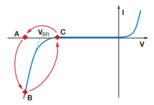
Figure 3.1 Current Voltage Characteristics of an Avalanche Photodiode Operated in Geiger Mode
Afterwards the excess bias voltage can be restored. During this time, which is known as the pulse dead time of the diode, the APD is insensitive to any other incoming photons. Spontaneously triggered avalanches are possible while the diode is in a metastable state. If these spontaneous avalanches occur randomly, they are called dark counts. If the spontaneously triggered avalanches are correlated in time with a pulse caused by a photon, it is called an afterpulse. To block such afterpulses in the measurement, an additional pulse dead time can be set in the software for the counting modules, which will cause the internal counter of the single photon detector to ignore all pulses occurring during this pulse dead time.
Definitions
Geiger Mode:
In this mode, the diode is operated slightly above the breakdown threshold voltage. Hence, a single electron-hole pair (generated by absorption of a photon or by a thermal fluctuation) can trigger a strong avalanche.
Dark Count Rate:
This is the average rate of registered counts in the absence of any incident light and determines the minimum count rate at which the signal is dominantly caused by real photons. The false detection events are mostly of thermal origin and can therefore be strongly suppressed by using a cooled detector.
Active Quenching occurs when a fast discriminator senses the steep onset of the avalanche current and quickly reduces the bias voltage so that it is below breakdown momentarily. The bias is then returned to a value above the breakdown voltage in preparation for detection of the next photon.
Dead Time is the time interval the detector spends in its recovery state. During this time, it is effectively blind to incoming photons. The dead time fraction, which is an inherent feature of an active quenching circuit, may be defined as the ratio of missed to incident events.
Afterpulsing:
During an avalanche, some charges can be trapped inside the high field region. When these charges are released, they can trigger an avalanche. These spurious events are called Afterpulses. The life of those trapped charges is on the order of a few tenths of a microsecond. Hence, it is likely that an afterpulse occurs directly after a signal pulse.
SOFTWARE
Software for SPCMxxA(/M) Counter Modules
Version 1.1
Click the button below to visit the software page for these Single Photon Counters.
Software for SPCMxxA(/M) Counting Modules
The SPCMxxA(/M) Single Photon Counting Modules include a software package with GUI for out-of-the-box operation. Please note the SPDMA and SPDMHx Single Photon Detectors do not include or require any software for operation.
The following operating modes can be set by the software:
Manual Mode:
The counter is started and stopped manually by pressing the Start/Stop button (toggle function). The timer will be reset at each start.
Free Running Timer Counter:
Both the number of time bins (i.e, the number of measurements) as well as the minimum interval between two subsequent bins can be set.
Externally Triggered Timer Counter:
In this mode, the timer is started by an external trigger signal and counts incident photons during the set time bin length. The active trigger slope (rising or falling) can be selected.
Externally Triggered Counter:
In this mode, the external trigger signal will start and stop the counter.
External Gating:
The counter and the APD are activated externally.
Measurement Settings:
In the array mode, each data value is recorded to an array. In the continuous mode, the measurement is restarted after the preset number. Both modes can be saved as a .txt file. The measurement results can be represented as a bar (XY bar with counts vs. number of measurements), graph (curve), table (numeric) or alignment (numeric with additionally information) display. The number of measurements can be defined, and the measurements can be repeated.
Optical Parameter Monitor (OPM) Software
Version 7.0
Click on the link below to download the Optical Parameter Monitor (OPM) Software.
Optical Parameter Monitor GUI Software for SPCNT Counters
Features
- Record and Analyze Measurements in Real Time
- Intuitive Numeric Display and Graphing Modes
- Configurable Long-Term Data Logging
- Connect up to 8 SPCNT Counters in Parallel
Multiple data measurement and analysis functions are integrated into the GUI package. The interface offers a user-friendly design with minimal use of color and low brightness that is ideal for use in dark lab environments while wearing laser safety glasses. Measured data can be displayed in real time as digital values or a line graph. Continuously logged and short-term measurements can be recorded for data viewing and analysis at a later point. A built-in statistics mode analyzes measured data and continuously updates to reflect new measurements within the pre-determined measurement period.
The Optical Parameter Monitor software package installs the GUI, which then can be used to control the USB-interface SPCNT console. Programming examples and drivers for interfacing with all supported devices using LabVIEW, C/C++, Visual C#, and Python are installed with the software.
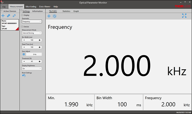
Click to Enlarge
Figure 3.1 Measurement Panel: The Measurement Panel displays the frequency data or numeric counts as set in the settings panel.
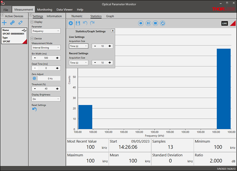
Click to Enlarge
Figure 3.2 Measurement Statistics: The numerical statistics for a pre-determined measurement period are calculated. The panel displays the analyzed values in a bar graph and the results as numerical values.
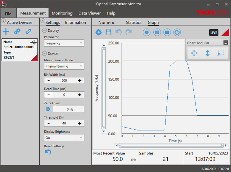
Click to Enlarge
Figure 3.3 Graph Panel: The Graph Panel shows the signal over time either as frequency or counts.
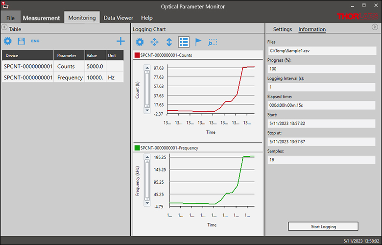
Click to Enlarge
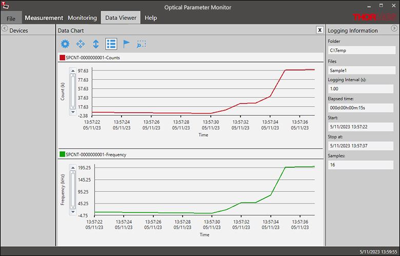
Figure 3.4 Data Logging: The Logging Chart enables long-term measurement and simultaneous recording from up to eight photon counters. Data can be saved as .csv files for later processing while measurement results are displayed in a graph in real time.
Click to Enlarge
Figure 3.5 Data Viewer: The logged data can be loaded and displayed.
Single Photon Detection Module with Adjustable Gain
- Extended Wavelength Range: 350 nm - 1100 nm
- Adjustable Gain
- Compact Size: 72.0 mm x 51.3 mm x 27.4 mm
- Ø500 μm Active Detector, Concentrically Aligned to Input Aperture
The SPDMA Single Photon Detection Module provides an extended photon detection efficiency (PDE) into the NIR. The adjustable gain allows the user to optimize for either higher PDE (higher gain) or lower dark counts (lower gain). The status LED on the side of the module has a cover to prevent LED light from disturbing the measurement.
For flexible integration into optical systems, the detection module has external SM1 (1.035"-40) threading for compatibility with Ø1'' lens tubes as well as four 4-40 tapped holes for integration with 30 mm cage components. The SPDMA module can be mounted in metric or imperial systems using the three 8-32 and M4 combi-thread mounting holes, located on both sides and the bottom of the unit.
Click to Enlarge
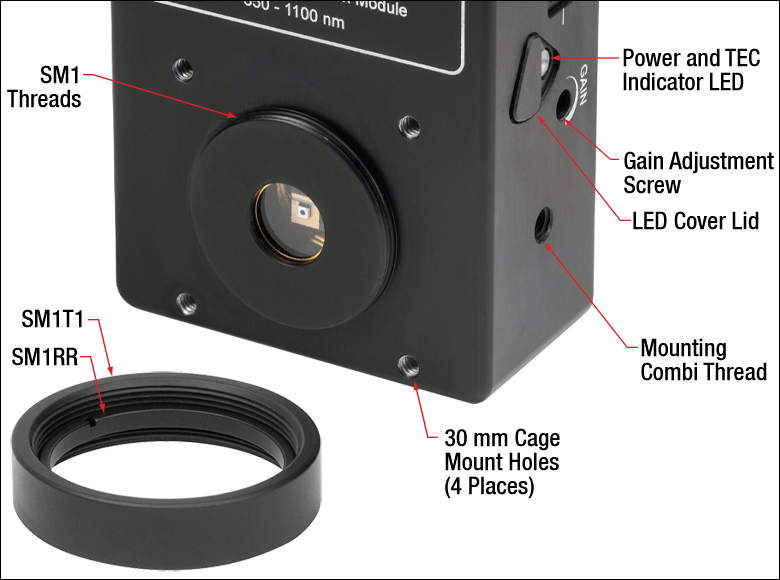
Figure G1.1 The SPDMA detection module has external SM1 threads, is 30 mm cage system compatible, and includes an SM1T1 Internal SM1 Adapter and SM1RR Retaining Ring. The module also includes a gain adjustment screw and status LED with cover.
The detection module includes an SM1T1 SM1 coupler that adapts the external thread to an internal thread, an SM1RR retaining ring, and a reusable protective plastic cover cap. A power supply with a region-specific plug is also included with the module.
| Item # | SPDMAa |
|---|---|
| Detector Type | Si Avalanche Photodetector |
| Wavelength Range | 350 nm - 1100 nm |
| Photon Detection Efficiency | |
| Active Detector Size | Ø500 µm |
| Gain Adjustment Factor (Typical) | 4 |
| Typical Photon Detection Efficiency (@ Max Gain) |
58% @ 500 nm 66% @ 650 nm 43% @ 820 nm |
| Dark Count Rate |
<75 Hz (Typical); <400 Hz (Max) @ Min Gain <300 Hz (Typical); <1500 Hz (Max) @ Max Gain |
| Count Rate | 20 MHz (Typical @ Max Gain) |
Part Number | Description | Price | Availability |
|---|---|---|---|
SPDMA | Customer Inspired! Single Photon Detection Module, 350 - 1100 nm, Ø500 µm Active Area | $5,260.00 | Today |
Single Photon Detection Modules with Fixed Gain

| Table G2.1 Specifications | ||||
|---|---|---|---|---|
| Item # | SPDMH2a | SPDMH2Fa | SPDMH3a | SPDMH3Fa |
| Detector | ||||
| Detector Type | Si Avalanche Photodetector | |||
| Wavelength Range | 400 nm - 1000 nm | |||
| Photon Detection Efficiency |
||||
| Active Detector Sizeb | Ø100 µm (Nominal) | |||
| Typical Photon Detection Efficiencyc |
10% @ 405 nm 50% @ 520 nm 70% @ 670 nm 60% @ 810 nm |
|||
| Dark Count Rate (Max) |
100 Hz | 250 Hz | ||
| Count Rate | 20 MHz (Max) | |||
| Input Fiber Compatibility | ||||
| Fiber Connector | N/A | FC/PC | N/A | FC/PC |
| Input Fiber Core Diameter (Max) |
N/A | <105 μm | N/A | <105 μm |
| Numerical Aperture | N/A | ≤0.29 | N/A | ≤0.29 |
- Wavelength Range: 400 nm - 1000 nm
- Free-Space or FC/PC Connector Versions
- Maximum Dark Count Rate: 100 Hz or 250 Hz
- High Photon Detection Efficiency (See Table G2.1)
- Ø100 μm Active Detector (Nominal)
These SPDMHx Single Photon Detector Modules feature high photon detection efficiencies (PDEs) that extend into the NIR and low dark count rates, enabled by combining ultra-low-noise silicon avalanche photodiodes with specially developed quenching and signal processing electronics. Incoming photons generate corresponding electrical pulses that are converted into TTL pulses at the LEMO connector output. A LEMO to BNC adapter is included.
Versions are available with a maximum dark count rate of 100 Hz (Item #s SPDMH2 and SPDMH2F) or 250 Hz (Item #s SPDMH3 and SPDMH3F).
The detectors can be purchased in a free-space version (Item #s SPDMH2 or SPDMH3) that has internal SM1 (1.035"-40) threading for compatibility with Ø1'' lens tubes. We also offer versions with an FC/PC fiber optic receptacle that is pre-aligned to the detector, allowing a multimode fiber optic patch cable to be directly connected to the input (Item #s SPDMH2F or SPDMH3F).
For flexible integration into optical systems, there is an 8-32 tapped hole on each side of the input. The base plate of the detector can be mounted directly to an optical table or breadboard using CL4 Table Clamps. Alternatively, three Ø3.9 mm (Ø0.15") through holes on each side of the base plate accept 6-32 screws for compatibility with the BA4 mounting base. For the free-space detectors, we recommend mounting the BA4 mounting base to a 3-Axis translation stage or other positioning stage to enable precise alignment.
In order to avoid damage to the module, adequate heat sinking must be provided by placing or mounting the module onto a suitable heat sink, e.g. an optical table, breadboard or base plate. Avoid stray light impinging on the detector, which affects the count rate. Employ appropriate shielding for the SPDMH2 and SPDMH3 free space models and make sure that any optical fiber assembly attached to the FC/PC connector of the SPDMH2F or SPDMH3F modules shields unwanted light.
A power supply with a region-specific plug is included with each module.
Part Number | Description | Price | Availability |
|---|---|---|---|
SPDMH2 | Single Photon Detection Module, 400 - 1000 nm, Ø100 µm Active Area, 100 Hz Dark Count Rate | $6,090.84 | Today |
SPDMH2F | Single Photon Detection Module, 400 - 1000 nm, Ø100 µm Active Area, 100 Hz Dark Count Rate, FC/PC Connector | $6,629.44 | Today |
SPDMH3 | Single Photon Detection Module, 400 - 1000 nm, Ø100 µm Active Area, 250 Hz Dark Count Rate | $4,944.87 | Today |
SPDMH3F | Single Photon Detection Module, 400 - 1000 nm, Ø100 µm Active Area, 250 Hz Dark Count Rate, FC/PC Connector | $5,850.18 | Today |
Single Photon Counting Device

| Table G3.2 Specifications | |
|---|---|
| Item # | SPCNT |
| Power Supplya | |
| Connector | USB 2.0 |
| Voltage | 5 V |
| Current | 200 mA |
| Default Settings | |
| Bin Width | 500 ms |
| Dead Time | 0 ms |
| Threshold | 40% |
- Monitor Counts from Single Photon Detectors with Built in Display or PC
- Compatible with the SPDMA and SPDMHx Single Photon Detectors Single Photon Detectors
- Monitor and Save Results with Optical Parameter Monitor Software
- Monitor Output Connects to External Counters or Oscilloscope
- TRIG IN Connector to Gate via TTL signal
- Input Signals Up to 100 MHz
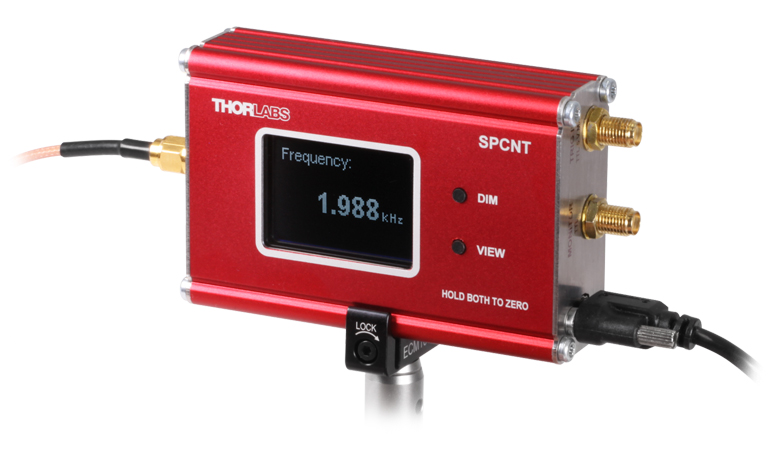
Thorlabs' SPCNT Single Photon Counting Device recognizes signal pulses originating from a connected single photon detector. The results are shown numerically as counts or frequency on the built in display or sent to a connected PC for display and analysis. The SPCNT counter is compatible with Thorlabs' SPDMA single photon detector with adjustable gain and the SPDMHx series of detectors series of detectors with fixed gain.
The SPCNT counter can be operated with or without a PC connection. When the SPCNT counter is connected to (and powered by) the PC via the USB 2.0 port (USB type A to mini-B cable included), the device can be controlled by Thorlabs' Optical Parameter Monitor (OPM) software, which can also monitor and save counting results - see the Software tab for details. When the SPCNT counter is directly operated without connection to a PC, the device must be powered by an external power supply. Please see Table G3.2 for the required power supply specifications. Thorlabs' DS5 power supply is recommended. While operating without a PC connection the default settings shown in the table are applied to the SPCNT photon counter.
The monitor output SMA connection provides access to the pulses of the input signal for use with an external counter or oscilloscope. The monitor output signal is not identical to the input signal, as the Schmitt Trigger compares the pulse input with a configurable threshold, above which the signal is counted. See chapter Operating Principle in the SPCNT device manual for details.
The SPCNT counter can be operated in Gated mode where an external active high TTL signal can be applied to define the bin width or dead time with external hardware such as a signal generator.
The ECM100 or ECM225 Aluminum Side Clamps can be used to securely mount the SPCNT counter conveniently in the laboratory.
Part Number | Description | Price | Availability |
|---|---|---|---|
SPCNT | Single Photon Counting Device | $600.27 | Today |
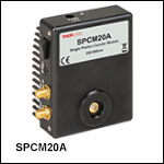
Single Photon Counting Modules
| Item # | SPCM20A(/M)a | SPCM50Aa |
|---|---|---|
| Detector Type | Si Avalanche Photodetector | |
| Wavelength Range | 350 nm - 900 nm | |
| Photon Detection Efficiency | ||
| Active Detector Size | Ø20 µm | Ø50 µm |
| Typical Photon Detection Efficiency | 35% @ 500 nm | |
| Dark Count Rate |
25 Hz (Typical) 60 Hz (Max) |
150 Hz (Typical) 200 Hz (Max) |
| Max Count Rate | 28 MHz | 22 MHz |
- Integrated Counter and Software Included
- Wavelength Range: 350 nm - 900 nm
- Compact Size: 85.0 mm x 76.5 mm x 36.2 mm
The SPCMxxA(/M) will be retired without replacement when stock is depleted. If you require this part for line production, please contact our OEM Team.
The SPCMxxA(/M) Single Photon Counting Modules convert an incoming photon to a TTL signal in the detector, which is then counted by an internal 31 bit counter. The module includes a software package with GUI for out-of-the-box operation. For more details about the software and its operation modes, please see the Software tab.
For flexible integration into optical systems, the detection module has external SM1 (1.035"-40) threading for compatibility with Ø1'' lens tubes. The SPCM20A(/M) provides an active area of Ø20 µm while the SPCM50A offers Ø50 µm. The Ø20 µm active area detector is offered with modules designed for imperial or metric systems, and the Ø50 µm active area detector is only offered for imperial mounting systems.
The module comes with a CD with the operating software, a USB 2.0 cable, Type A to mini Type B, and a power supply.
Part Number | Description | Price | Availability |
|---|---|---|---|
SPCM20A/M | Single Photon Counting Module, 350 - 900 nm, Ø20 µm Active Area, M4 Tap | $5,433.87 | Today |
SPCM20A | Single Photon Counting Module, 350 - 900 nm, Ø20 µm Active Area, 8-32 Tap | $5,433.87 | Lead Time |
SPCM50A | Single Photon Counting Module, 350 - 900 nm, Ø50 µm Active Area, 8-32 Tap | $6,043.98 | Today |