

Benchtop Brushless DC Motor Controllers
- One-, Two-, and Three-Channel Models Available
- Supports 3-Phase, Brushless DC Servo Motors (5 A Peak Total Output) with Encoder Feedback
- Direct Front Panel Control or Remote PC Operation
- Full Suite of Software Tools Available
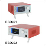
BBD301
1-Channel Controller
BBD303
3-Channel Controller
Kinesis Software GUI
OVERVIEW
| Benchtop Motion Controllers |
|---|
| 1-, 2-, and 3-Channel Brushless DC Servo Controllers |
| 1-, 2-, and 3-Channel Stepper Motor Controllers |
| 1- and 3-Channel Open Loop Piezo Controllers |
| 1- and 3-Channel Closed Loop Piezo Controllers |
| 2-Channel NanoTrak® Auto-Alignment Controller |
| Other Brushless DC Servo Controllers | |
|---|---|
| K-Cube® Single-Channel Controller | |
| Modular 2-Channel Rack System Module | |

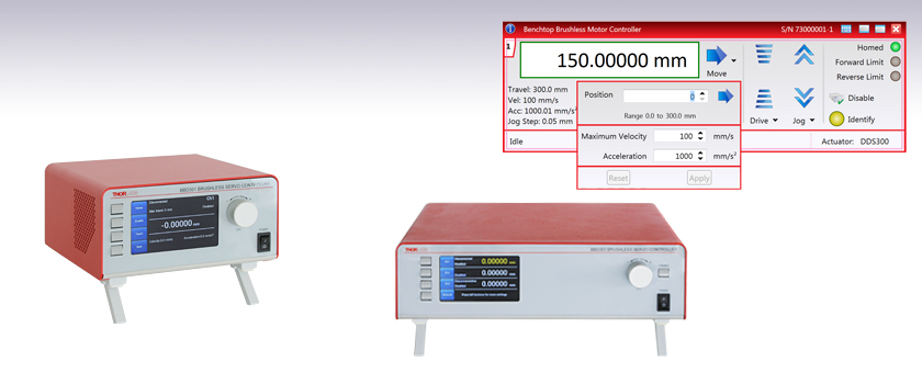
Click to Enlarge
Figure 1.1 BBD302 Front Panel
(Shown Connected to DDS220 Linear Stage and
DDR100 Rotation Stage)
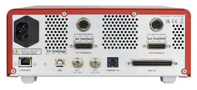
Click to Enlarge
Figure 1.2 BBD302 Rear Panel
Features
- Supports Thorlabs' Range of 3-Phase, Brushless DC Servo Motor Products
- Encoder Feedback for Closed-Loop Velocity and Position Control
- Front Panel Display and Control to Complement Remote PC Operation
- AUX I/O Port Exposes RS232 Communications and Digital Input and Output Signals
- USB and Ethernet Connectivity
- Supported by the Kinesis and XA Software Control Suites
- Features Supported by Software:
- Synchronized Moves
- PID Settings
- Seamless Integration with All Kinesis Family Controllers
- Compact Controller Footprints (See the Specs Tab for Details)
The BBD300 Series of Brushless DC Motor Controllers are ideal for motion control applications demanding operation at high speeds (hundreds of mm/s) and with high encoder resolution (<100 nm). These controllers offer one, two, or three channels of high-precision motion control for a wide range of applications, particularly microscopy sample manipulation if paired with our MLS203 Series of Dual-Axis Scanning Stages or general motion applications using our 150 mm, 220 mm, 300 mm, or 600 mm translation stages or our direct drive rotation stage. For integration into our MMR601 Rack System Enclosure please see our MBD602 Controller Module.
USB connectivity provides easy plug-and-play PC operation. Multiple units can be connected to a single PC via standard USB hub technology for multi-axis motion control applications. The BBD300 series controllers are fully compatible with Thorlabs' XA and Kinesis software applications, allowing users to operate devices with reasonably complex move sequences in a short period of time. Note that the MBD602 controller is not currently supported by our XA software application, but is fully compatible with our Kinesis software. Using either software application, all relevant operating parameters are set automatically for Thorlabs stage and actuator products. Advanced custom motion control applications and sequences are also possible using the extensive programming environment described in more detail on the Kinesis and XA Software tab. These controls can be incorporated into a wide range of software development environments including LabVIEW, C++, and MATLAB.
Cabling
Cables for connecting actuators or stages to the controller are shipped with the actuators or stages, not the controller. If you need help identifying the appropriate replacement cable, please contact Tech Support.
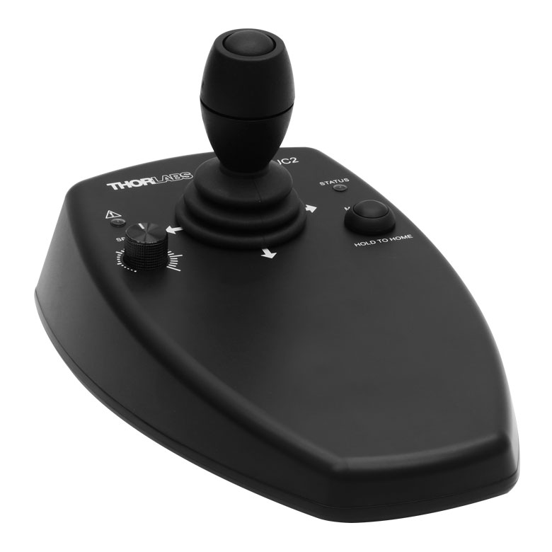
Click to Enlarge
Figure 1.3 MJC2 Joystick for X-Y Axis Control
Comparison to BBD200 Series Controllers
Our BBD300 series controllers represent a significant upgrade in capabilities compared to our previous-generation BBD200 series controllers. The new front panel enables direct control of attached stages via manual controls and LCD output of key parameters including velocity and position, regardless of whether the unit is connected to a PC. Also, synchronized moves can now be configured in multi-channel versions, enabling advanced contouring movements. Lastly, the user can now control the PID motor settings, allowing adjustments to account for different load inertias and optimization of movement.
Not For Use with Brushed DC Motors
This controller is designed for use with high-power, brushless DC servo motors. For control of the Thorlabs brushed DC servo motor devices, please see the KDC101 DC Servo Motor Driver K-Cube®.
Optional Joysticks
The MJC2 and MJC3 joysticks have been designed for microscope users, to provide intuitive, tactile, manual positioning of the stage. The joysticks feature a two-axis joystick knob for XY control or a three-axis joystick knob for XYZ control, respectively. In most applications, the default parameter settings saved within the controller allow the joystick to be used out-of-the-box, with no need for further setup, thereby negating the requirement to be connected to a host PC, and allowing true remote operation.
SPECS
| Item # | BBD301 | BBD302 | BBD303 |
|---|---|---|---|
| Number of Channels | 1 | 2 | 3 |
| Drive Connector | 8 Pin DIN, Round, Female | ||
| Feedback Connector | 15-Pin D-Type, Female | ||
| Brushless Continuous Output | 2.5 A per Channel, 5 A Max All-Channel Total Output | ||
| Brushless Peak Output | 4.0 A per Channel, 5 A Max All-Channel Total Output | ||
| PWM Frequency | 40 kHz | ||
| Operating Modes | Position and Velocity | ||
| Control Algorithm | 16-Bit Digital PID Servo Loop with Velocity and Acceleration Feedforward |
||
| Velocity Profile | Trapezoidal/S-Curve | ||
| Position Count | 32 Bit | ||
| Position Feedback | Incremental Encoder | ||
| Encoder Bandwidth | 2.5 MHz (10 M Counts/sec) | ||
| Encoder Supply | 5 V | ||
| AUX Control Connector | 37-Pin D-Type Female (User Digital IO, 5 V O/P) | ||
| Front Panel Display | 4.3" Full-Color LCD, 480 x 272 Pixels | ||
| Input Power Requirements |
250 VA Voltage: 100 to 240 VAC Frequency: 47 to 63 Hz Fuse: 3.15 A |
||
| Dimensions (W x D x H) | 199.8 mm x 229.1 mm x 108.8 mm (7.87" x 9.02" x 4.28") |
250.0 mm x 279.1 mm x 108.8 mm (9.84" x 10.99" x 4.28") |
350.0 mm x 279.1 mm x 108.8 mm (13.78" x 10.99" x 4.28") |
| Mass (Weight) | 1.20 kg (2.65 lbs) | 1.70 kg (3.75 lbs) | 2.20 kg (4.85 lbs) |
FRONT PANEL
Front Panel Features
Our BBD300 series controllers can be used to drive attached stages directly via the front panel controls and display, without the specific need of a computer connection and its peripheral software; only a mains power connection is needed, together with electrical connections to each stage. Below is a quick overview of functionality for the BBD301 single-channel controller.
| Stage Control Screen (Stationary Stage) | Stage Control Screen (Stage in Motion) | ||
|
|
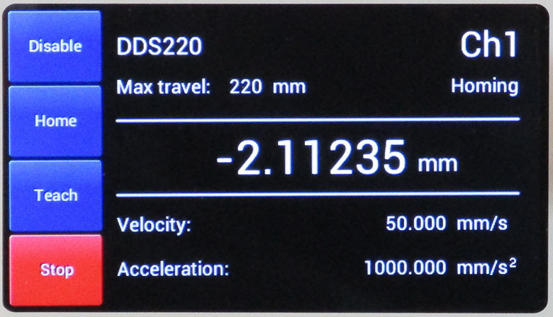
After start-up and selecting the required channel (for multi-channel controllers), the display provides information on the stage connected to the channel, stage parameters, and status information. The stage can be enabled and homed simply by using the two touch buttons to the left of the screen. |
|
During any stage movement (in this case, while homing), the stage can be stopped by pressing the STOP button that becomes highlighted when the stage is in motion. This is useful if there are any unforeseen impediments to motion or the wrong run sequence is initiated. |
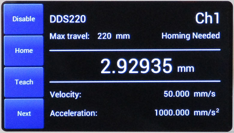
| Motor Parameters | Editing Motor Parameters | ||
|
|
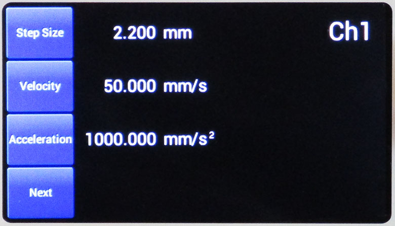
Stage travel parameters can be seen at a glance and changed (see next screen). |
|
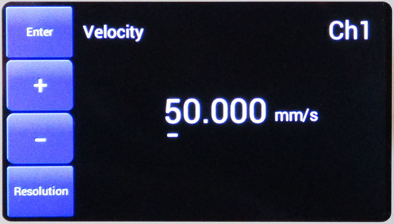
Changing any of the set parameters is simple and intuitive, as seen here for stage velocity. |
| Position Setpoints | General Settings | ||
|
|
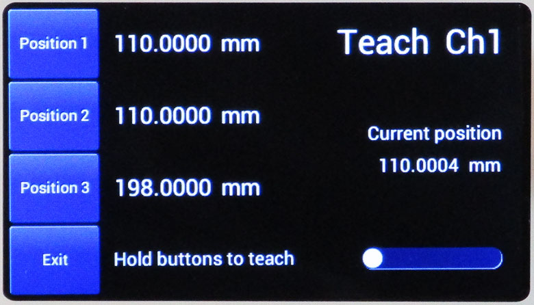
Under the Teach menu, several position setpoints can be programmed using the knob and touch buttons. Once the stage position has been reached, press and hold the position touch button to record the position to firmware. The stage can then be sent directly to these positions by pressing the touch button next to the position required. |
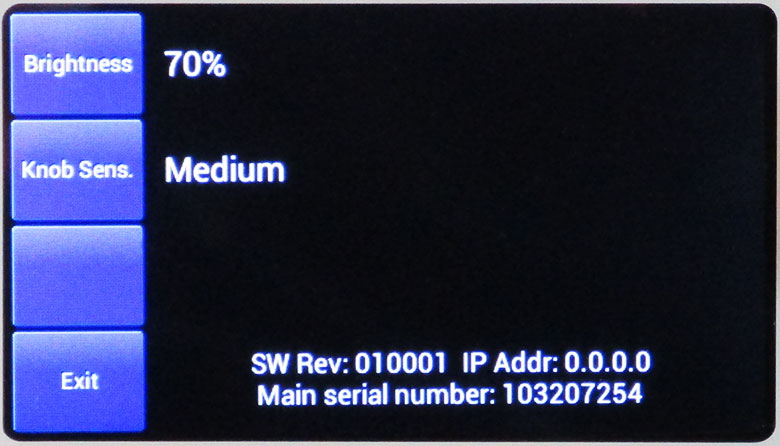
|
Screen brightness and knob sensitivity can also be changed. This screen also displays the firmware version, IP address, and controller serial number. |
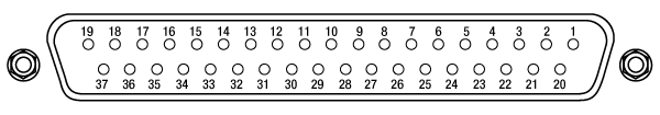
PIN DIAGRAMS
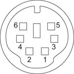
MOTOR DRIVE
Female DIN Connector
| Pin | Description | Pin | Description |
|---|---|---|---|
| 1 | Motor Phase B | 5 | Stage ID |
| 2 | GND | 6 | Enable |
| 3a | Unused (Motor Phase D) | 7 | Motor Phase C |
| 4 | Motor Phase A | 8a | +5 V |
FEEDBACK
Female D-Type Connector
| Pin | Description | Pin | Description |
|---|---|---|---|
| 1 | Not Connected | 9 | GND |
| 2 | GND | 10 | Limit Switch + |
| 3 | Not Connected | 11 | Limit Switch - |
| 4 | Index - | 12 | Index + |
| 5 | QB - | 13 | QB + |
| 6 | QA - | 14 | QA + |
| 7a | 5 V | 15 | Not Connected |
| 8a | 5 V |
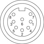
HANDSET
Female Mini DIN Connector
| Pin | Description | Pin | Description |
|---|---|---|---|
| 1 | RX (Controller Input) |
4 | Supply Voltage for Handset 5 V |
| 2 | Ground | 5 | TX (Controller Output) |
| 3 | Ground | 6 | Ground |
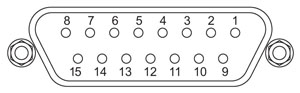
AUX I/O
Female D-Type Connector
| Pin | Description | Pin | Description | Pin | Description | Pin | Description |
|---|---|---|---|---|---|---|---|
| 1 | RS232 TX | 11 | User Digital O/P 11+ | 21 | +5 V | 31 | User Digital O/P 4+ |
| 2 | RS232 RX | 12 | User Digital O/P 10- | 22 | User Digital I/P 3 | 32 | User Digital O/P 4- |
| 3 | Ground | 13 | User Digital O/P 10+ | 23 | User Digital I/P 2 | 33 | User Digital O/P 5+ |
| 4 | Differential I/P 2+ | 14 | User Digital O/P 9- | 24 | User Digital I/P 1 | 34 | User Digital O/P 5- |
| 5 | Differential I/P 2- | 15 | User Digital O/P 9+ | 25 | User Digital I/P 0 | 35 | User Digital O/P 6+ |
| 6 | Differential I/P 1- | 16 | User Digital O/P 8- | 26 | User Digital O/P 0 | 36 | User Digital O/P 6- |
| 7 | Differential I/P 1+ | 17 | User Digital O/P 8+ | 27 | User Digital O/P 1 | 37 | Ground |
| 8 | User Digital O/P 12- | 18 | User Digital O/P 7- | 28 | User Digital O/P 2 | - | - |
| 9 | User Digital O/P 12+ | 19 | User Digital O/P 7+ | 29 | User Digital O/P 3 | ||
| 10 | User Digital O/P 11- | 20 | +5 V | 30 | Ground |
USB
Type B USB Female

I/O
Female BNC Connector
5 V TTL
KINESIS AND XA SOFTWARE
Software
Kinesis Version 1.14.58
XA Version 1.6.0
The Kinesis and XA Software Packages, which include a GUI for control of Thorlabs' motion controllers.
Also Available:
- Firmware Update Utilities
- Communications Protocol

Figure 789A Kinesis GUI Screen
Thorlabs offers two platforms to drive our wide range of motion controllers: our XA software package and our Kinesis software package, which is being phased out. The Kinesis software supports most of Thorlabs' motion control products. The XA software is an improved platform for developers that currently supports some of our most popular motion control products (see the full list of supported products here). The software is undergoing continuous, intensive development and will eventually add support for our entire line of motion control products. The XA software application will be fully supported through the year 2040.
Kinesis Motion Control Software
The Kinesis software features .NET controls which can be used by 3rd party developers working in the latest C#, Visual Basic, LabVIEW™, or any .NET compatible languages to create custom applications. Low-level DLL libraries are included for applications not expected to use the .NET framework. A Central Sequence Manager supports integration and synchronization of all Thorlabs motion control hardware.
By providing a common software platform, Thorlabs has ensured that users can easily mix and match any of the Kinesis controllers in a single application, while only having to learn a single set of software tools. In this way, it is perfectly feasible to combine any of the controllers from single-axis to multi-axis systems and control all from a single, PC-based unified software interface.
Click to Enlarge
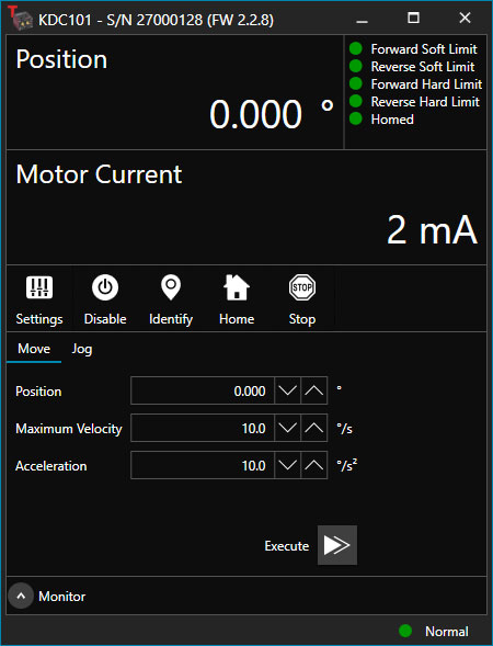
Figure 789B XA GUI for KDC101 Brushed DC Servo Controller
The software package allows two methods of usage: graphical user interface (GUI) utilities for direct interaction with and control of the controllers out of the box, and a set of programming interfaces that allow custom-integrated positioning and alignment solutions to be easily programmed in the development language of choice.
XA Motion Control Software: Improved Platform for Developers
Designed from the ground up to be straightforward to understand, XA provides a thread-safe and language-paradigm-agnostic set of application programming interfaces in C, C++, and C#/.NET with language wrappers available to allow for easy integration into your native, .NET language, Python, or LabVIEW applications. This enables the same functionality as mentioned for the Kinesis software development kit (SDK) while providing a more streamlined toolkit for developers. Coupled with the included developer guides and code examples in the SDK, this software is tailored toward users interested in creating complex, customized applications and interfaces. Full API documentation is provided for the native C library, and the .NET wrapper documentation is currently under development. Please contact Tech Support for more details on using the .NET wrapper.
XA also features a comparable GUI to Kinesis while adding improvements to the user experience, like the ability to save device states and a more consistent interface across devices of different types. In addition, further improvements are planned as XA will be fully supported through the year 2040, whereas the Kinesis software is being phased out. The current version of the XA software can only drive select Thorlabs motion controllers. However, the software is undergoing continuous, intensive development and will eventually add support for our entire line of motion control products. Information on software compatibility can be found in the XA User Guide, and additional details about the software, including a list of compatible devices, can be found here.
KINESIS TUTORIALS
Thorlabs' Kinesis software features new .NET controls which can be used by third-party developers working in the latest C#, Visual Basic, LabVIEW™, or any .NET compatible languages to create custom applications.
C#
This programming language is designed to allow multiple programming paradigms, or languages, to be used, thus allowing for complex problems to be solved in an easy or efficient manner. It encompasses typing, imperative, declarative, functional, generic, object-oriented, and component-oriented programming. By providing functionality with this common software platform, Thorlabs has ensured that users can easily mix and match any of the Kinesis controllers in a single application, while only having to learn a single set of software tools. In this way, it is perfectly feasible to combine any of the controllers from the low-powered, single-axis to the high-powered, multi-axis systems and control all from a single, PC-based unified software interface.
The Kinesis System Software allows two methods of usage: graphical user interface (GUI) utilities for direct interaction and control of the controllers 'out of the box', and a set of programming interfaces that allow custom-integrated positioning and alignment solutions to be easily programmed in the development language of choice.
For a collection of example projects that can be compiled and run to demonstrate the different ways in which developers can build on the Kinesis motion control libraries, click on the links below. Please note that a separate integrated development environment (IDE) (e.g., Microsoft Visual Studio) will be required to execute the Quick Start examples. The C# example projects can be executed using the included .NET controls in the Kinesis software package (see the Kinesis Software tab for details).
 |
Click Here for the Kinesis with C# Quick Start Guide Click Here for C# Example Projects Click Here for Quick Start Device Control Examples |
|
LabVIEW
LabVIEW can be used to communicate with any Kinesis-based controller via .NET controls. In LabVIEW, you build a user interface, known as a front panel, with a set of tools and objects and then add code using graphical representations of functions to control the front panel objects. The LabVIEW tutorial, provided below, provides some information on using the .NET controls to create control GUIs for Kinesis-driven devices within LabVIEW. It includes an overview with basic information about using controllers in LabVIEW and explains the setup procedure that needs to be completed before using a LabVIEW GUI to operate a device.
 |
Click Here to View the LabVIEW Guide Click Here to View the Kinesis with LabVIEW Overview Page |
|
Benchtop Brushless DC Servo Controllers
- Controllers for 1-, 2-, or 3-Channel 3-Phase, Brushless DC Servo Motor Products
- Ideal for High Speed, High Precision Motion Control Applications
- Front Panel Display and Control
- USB, Ethernet, and AUX I/O Ports for Communication and Plug-and-Play PC Operation
- Supported by Kinesis and XA Software Control Suites
- Compact Controller Footprints
The BBD300 Series of Brushless DC Servo Motor Controllers are ideal for motion control applications demanding operation at high speeds (hundreds of mm/s) and high encoder resolution (<100 nm). Incorporating the latest digital and analog techniques as well as high-bandwidth, high-power servo control circuitry, each BBD series controller is designed to drive brushless DC servo motor products with continuous output currents of up to 2.5 A (Item # BBD301) or 5 A (Item #s BBD302 and BBD303). With a user-configurable S-curve acceleration/deceleration profile that enables fast, smooth positioning without vibration or shock, these controllers are particularly useful for microscopy sample manipulation when paired with our MLS203 Series of Dual-Axis Scanning Stages or general motion applications using our 150 mm, 220 mm, 300 mm, or 600 mm translation stages or our direct drive rotation stage.
These DC servo controllers are supported by Thorlabs' Kinesis and XA control and programming interfaces, enabling easy integration into automated motion control applications. For greater flexibility, both a USB and RS232 computer interface is provided, and automated PC control of the stage is supported with the supplied software development kit (SDK). The fully documented SDK supports all major development languages running on Windows and comes in the form of a conventional dynamic link library (DLL). For more information please see the Kinesis and XA Software tab.
USB connectivity provides easy plug-and-play PC operation. Multiple units can be connected to a single PC via standard USB hub technology for multi-axis motion control applications. Combining this feature with our user-friendly software allows the user to program and carry out complex move sequences in a short space of time.
Part Number | Description | Price | Availability |
|---|---|---|---|
BBD301 | Customer Inspired! 1-Channel Benchtop 3-Phase Brushless DC Servo Controller | $2,584.51 | Today |
BBD302 | Customer Inspired! 2-Channel Benchtop 3-Phase Brushless DC Servo Controller | $3,902.56 | Today |
BBD303 | Customer Inspired! 3-Channel Benchtop 3-Phase Brushless DC Servo Controller | $4,957.53 | Today |
2-Axis and 3-Axis Joysticks
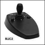
- High-Reliability Joysticks Utilizing USB HID Protocol
- 2-Axis or 3-Axis Control Via a Joystick Knob
- Two Different Modes for Fast or High Precision Moves
- Speed Dial for Sensitivity Adjustment
- Allows Remote Manual Control
- Can be Reprogrammed using a PC
- Ergonomic Design
The MJC2 and MJC3 Joysticks have been designed for microscope users and provide intuitive, tactile, manual positioning of a stage. The joysticks feature a two-axis joystick knob for XY control or a three-axis joystick knob for XYZ control, respectively. Both joystick knobs can be moved left or right and up or down, with the MJC3 joystick knob also twisting clockwise or counterclockwise for third axis control. A push button to switch between fast or high-precision movement and a speed dial to fine tune speed control are also integrated into the joysticks. In most applications, the default parameter settings saved within the controller allow the joystick to be used out-of-the-box with no need for further setup. This operation mode eliminates the need for connection to a host PC and allows for true remote operation. Parameter settings can also be reprogrammed and saved to a paired controller using a PC, allowing the controller to be disconnected from the computer and remote operation continued.
The MJC2 and MJC3 Joysticks are compatible with our Benchtop Brushless DC Servo Controllers, Rack-Mounted Brushless DC Servo Controller, Modular 2-Channel Brushless DC Servo Controller Rack System Module, and Stepper Motor Controllers. The joysticks have both a Mini-DIN and a USB Type-C port and are each shipped complete with two cables, a 6-pin Mini-DIN plug to plug cable and a USB 3.1 Type-A to Type-C cable, for use with these controllers as well as setups utilizing the USB HID class. For more information about configuring and setting up the joystick over USB HID, please see the manual by clicking on the red Docs icon ( ) below.
Part Number | Description | Price | Availability |
|---|---|---|---|
MJC2 | 2-Axis USB HID Joystick | $600.27 | Today |
MJC3 | 3-Axis USB HID Joystick | $638.47 | In Stock Overseas |