

12 W Laser Diode Temperature Controller
- Low Noise TEC Current: ±2 A
- Excellent Temperature Stability: ≤0.002 °C
- Separate P, I, and D-Gain Control
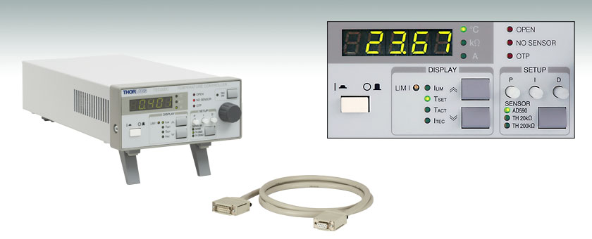
TED200C Front Panel (°C Display when Used with the AD590
Temperature Transducer, kΩ when Used with a Thermistor)
TED200C
CAB420-15
OVERVIEW
| Key Specifications | |
|---|---|
| Control Range | -2 A to 2 A |
| Compliance Voltage | >6 V |
| Maximum Output Power | 12 W |
| Control Range | 10 Ω to 20 kΩ / 100 Ω to 200 kΩ (2 Ranges) |
| Supported Sensors | AD590, AD592, LM135, LM335 |
Features
- Compatible Sensors: Thermistors, AD590/AD592, LM335
- TEC Output (Low Noise): ±2 A / 12 W
- Temperature Range from -45 °C to +145 °C (AD590) or 10 Ω to 200 kΩ (Thermistor)
- Temperature Resolution: 0.01 °C (IC-Sensor) or 1 Ω (Thermistor)
- Temperature Stability: ≤0.002 °C
- Separate Adjustment of the P, I and D Share of the Control Loop for Shortest Temperature Settling Time
- Constant Temperature Operating Mode
- Analog Control via the TUNE IN Input
- Adjustable TEC Current Limit
- Detection of Incorrect or Missing Temperature Sensor and Open TEC Connection
- RoHS Compliant
Applications
- Precise Stabilization of Laser Diodes for Use in Interferometry and Spectroscopy
- Cooling of Detectors for Noise Reduction
- Temperature Stabilization of Non-linear Crystals
- Temperature Stabilization of Industrial Systems
- Control Temperature Set Point via External Input for Active Stabilization of Laser Wavelength
Introduction
The TED200C is a precision temperature controller designed to drive thermoelectric cooler (TEC) elements with currents up to ±2 A. It supports almost all common temperature sensors and can be adapted to different thermal loads. A set of safeguard features and error indicators protects the connected TE coolers and laser diodes from damage. For an easy connection with external devices, or integration into control loops, the TED200C can be controlled via an analog voltage input and output. For higher currents, up to ±15 A, please see the TED4000 Temperature Controller Series.
Thorlabs recommends recalibrating these controllers every 24 months and offers a factory recalibration service. To order this service, scroll to the bottom of the page and select Item # CAL-TED2.
Note: The updated TED200C is now RoHS compliant. The rest of the features are virtually the same as the obsoleted product TED200.
Operation
The integrated 5-digit display of the TED200C shows the actual temperature reading, the set temperature, the heating or cooling current, or the current limit for the TE cooler. If used with a thermistor sensor, the TED200C will indicate the resistance (as opposed to the actual temperature); correlated temperatures can be calculated manually using the equation found in section 3.1.3.1 of the manual. The temperature set point can be controlled either by adjusting the large front panel control knob or via external signal input into the analog input connector at the rear of the controllers. The latter can be used in control loop mode for locking the wavelength of the laser diode by adjusting the temperature.
Adaptability to Different Thermal Loads
The TED200C can easily be adapted to different thermal loads using the PID feedback circuit that allows the user independent setting of the P (proportional) gain, the I (integral) offset control, and the D (derivative or differential) rate. The proportional gain optimizes the response time of the feedback loop, while the integral gain provides precise zero-offset regulation. The derivative gain optimizes the dynamic response of the feedback loop to accommodate rapid changes in the thermal load. With optimum PID adjustment the settling time is less than 2 seconds for a temperature change from 30 °C to 20 °C for a laser in a butterfly package mounted in our LM14S2 laser diode mount (using a butterfly package with integrated thermistor). The PID controls are located on the front panel for easy access when optimizing the response of the controller.
Supported Temperature Sensors
The TED200C Temperature Controller supports most common temperature sensors. A sensor selection switch allows the use of thermistors up to 200 kΩ or a temperature sensing IC (AD590, AD592, and LM335).
When a thermistor is selected, the temperature is displayed as the resistance value of the thermistor. When an AD590, AD592, or an LM335 is selected, the temperature is displayed in degrees Celsius, with a temperature set range of -45 °C to +145 °C. The actual control range is limited by the temperature rating of the connected IC sensor.
TEC Protection Features
The TED200C is designed for maximum TEC element protection. The limit adjustment of the TEC output current prevents the controller from overdriving the TEC element. This limit can be set anywhere within the current range of the controller.
Error Indication
The system indicates the presence of an incorrect or missing temperature sensor, or a bad connection between sensor and controller by an error LED together with an acoustic warning signal, and the TEC current is automatically switched off.
Temperature Monitor Output
For monitoring purposes, the TED200C provides an output voltage signal that is proportional to the actual temperature being measured. The signal is accessed via a BNC connector located on the back panel. This feature allows long term temperature recording of a device.
Companion Products
The LDC200 Laser Diode Controller Series is an ideal companion for the TED200C. When combined with our TEC laser mounts, the TED200C can achieve a thermal stability of 1 mK, robust enough for applications like diode laser wavelength tuning and atomic absorption cell spectroscopy.
Connection Cables
A CAB420-15 is required to connect the TED200C to a Thorlabs' Laser Diode Mount. One cable is included with the TED200C, it has a length of 1.5 m. Additional cables can be ordered below.
SPECS
| TED200C Specifications | |
|---|---|
| TEC Current Output | |
| Control Range | -2 A to 2 A |
| Compliance Voltage | >6 V |
| Maximum Output Power | 12 W |
| Measurement Resolution | 1 mA |
| Accuracy | ±10 mA |
| Noise and Ripple (Typ.) | <1 mA |
| TEC Current Limit | |
| Setting Range | 0 to >2 A |
| Measurement Resolution | 1 mA |
| Accuracy | ±20 mA |
| Thermistor Sensorsa | |
| Control Range | 10 Ω to 20 kΩ / 100 Ω to 200 kΩ (2 Ranges) |
| Setting Resolution (20 kΩ / 200 kΩ Range) |
1 Ω / 10 Ω |
| Measurement Resolution (20 kΩ / 200 kΩ Range) |
1 Ω / 10 Ω |
| Accuracy (20 kΩ / 200 kΩ Range) | ±10 Ω / ±100 Ω |
| Temperature Stability (24 Hours)b (20 kΩ / 200 kΩ Range) |
<0.5 Ω / <5 Ω |
| IC Sensors | |
| Supported Sensors | AD590, AD592, LM135, LM335 |
| Control Range with AD590, LM135 | -45 °C to 145 °C |
| Control Range with AD592 | -25 °C to 105 °C |
| Control Range with LM335 | -40 °C to 100 °C |
| Setting Resolution | 0.01 °C |
| Measurement Resolution | 0.01 °C |
| Accuracy (Except LM335) | ±0.1 °C |
| Temperature Stability (24 Hours) | <0.002 °C |
| Temperature Control Input | |
| Input Resistance | 10 kΩ |
| Control Voltage | -10 V to +10 V |
| Transmission Coefficient Thermistor (20 kΩ / 200 kΩ Range) |
2 kΩ/V / 20 kΩ/V ± 5% |
| Transmission Coefficient IC-Sensors |
20°C/V ± 5% |
| Temperature Control Output | |
| Load Resistance | >10 kΩ |
| Transmission Coefficient Thermistor (20 kΩ / 200 kΩ Range) |
500 mV/kΩ / 50 mV/kΩ ± 5% |
| Transmission Coefficient IC-Sensors |
50 mV/°C ± 5% |
| General Data | |
| Safety Features | TEC Current Limit, Short Circuit When TEC Off, No Sensor Protection, Open Circuit Detection, Over Temperature Protection |
| Display | LED, 5 Digits |
| Connector for Sensor, TE Cooler, TEC On Signal | 15-Pin D-Sub Jack |
| Connectors for Control Input / Output | BNC |
| Chassis Ground Connector | 4 mm Banana Jack |
| Line Voltage | 100 V, 115 V, 230 V +15%/-10% Each |
| Line Frequency | 50 to 60 Hz |
| Maximum Power Consumption | 60 W |
| Mains Supply Overvoltage | Category II (Cat II) |
| Operating Temperature | 0 to 40 °C |
| Storage Temperature | -40 to 70 °C |
| Relative Humidity | Max. 80% Up to 31 °C, Decreasing to 50% at 40 °C |
| Pollution Degree (Indoor Use Only) | 2 |
| Operation Altitude | <2000 m |
| Warm-up Time for Rated Accuracy | 10 min |
| Weight | <3.1 kg |
| Dimensions (W x H x D) without Operating Elements | 146 mm x 66 mm x 290 mm |
| Dimensions (W x H x D) with Operating Elements | 146 mm x 77 mm x 320 mm |
All technical data valid at 23 ± 5 °C and 45 ± 15% relative humidity.
FRONT & BACK PANEL
TED200C Front Panel
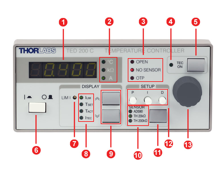
| Callout | Connection | Callout | Connection |
|---|---|---|---|
| 1 | 5-Digit LED Display | 8 | Display Indicators |
| 2 | Display Units | 9 | Up/Down Display Select |
| 3 | Interlock Indicators | 10 | Selected Sensor Inticators |
| 4 | TEC Status Indicator | 11 | Sensor Select Key |
| 5 | TEC Current On/Off Switch | 12 | Potentiometers for PID Gain Settings |
| 6 | Supply Power Switch | ||
| 7 | Potentiometer for Current Limit Setting | 13 | Display Adjustment Knob |
TED200C Back Panel

| Callout | Connection | Callout | Connection |
|---|---|---|---|
| 1 | Analog Temperature Control Input "Tune In", -10 to 10 V | 5 | 15-pin D-sub Jack for the TEC Element and the Temperature Sensor "TE OUTPUT" |
| 2 | Analog Temperature Control Output "CTL Out", -10 to 10 V | 6 | Serial Number of the Unit |
| 3 | Cooling Fan | 7 | Indicator / Switch for Line Voltage (Included in Fuse Holder) |
| 4 | 4 mm Banana Jack for Chassis Ground | 8 | Power Connector and Fuse Holder |
PIN DIAGRAMS
| Pin | Connection | Pin | Connection |
|---|---|---|---|
| 1 | Status LED (+) TEC ON/OFF | 9 | Not Connected |
| 2 | Not Connected | 10 | Transducer AD 590/592 (-), LM 135/335 (+) |
| 3 | Thermistor (-), Ground | 11 | Transducer AD 590/592 (+), LM 135/335 (+) |
| 4 | Thermistor (+) | ||
| 5 | TEC (+) | 12 | Not Connected |
| 6 | TEC (+) | 13 | TEC (-) |
| 7 | TEC (+) | 14 | TEC (-) |
| 8 | AGND LM 135/335 (-), Status LED (-) | 15 | TEC (-) |
Temperature Sensor and Controllera

Analog Temperature Control Input
-10 ... 10 V
Analog Temperature Control Output
-10 ... 10 V
Chassis Ground

SHIPPING LIST
| TED200C | Part |
|---|---|
| x | Benchtop Temperature Controller, ±2A/12 W (TED200C) |
| x | Cable for Temperature Controller with 15-pin D-Sub Connector (CAB420-15) |
| x | Operating Manual TED200C |
| x | Power Cord |
PID TUTORIAL
PID Basics
The PID circuit is often utilized as a control loop feedback controller and is commonly used for many forms of servo circuits. The letters making up the acronym PID correspond to Proportional (P), Integral (I), and Derivative (D), which represents the three control settings of a PID circuit. The purpose of any servo circuit is to hold the system at a predetermined value (set point) for long periods of time. The PID circuit actively controls the system so as to hold it at the set point by generating an error signal that is essentially the difference between the set point and the current value. The three controls relate to the time-dependent error signal. At its simplest, this can be thought of as follows: Proportional is dependent upon the present error, Integral is dependent upon the accumulation of past error, and Derivative is the prediction of future error. The results of each of the controls are then fed into a weighted sum, which then adjusts the output of the circuit, u(t). This output is fed into a control device, its value is fed back into the circuit, and the process is allowed to actively stabilize the circuit’s output to reach and hold at the set point value. Figure 101A illustrates the action of a PID circuit. One or more of the controls can be utilized in any servo circuit depending on system demand and requirement (i.e., P, I, PI, PD, or PID).
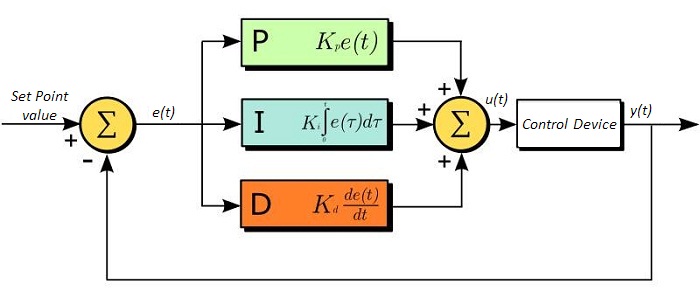 Figure 101A PID Diagram
Through proper setting of the controls in a PID circuit, relatively quick response with minimal overshoot (passing the set point value) and ringing (oscillation about the set point value) can be achieved. Let’s take as an example a temperature servo, such as that for temperature stabilization of a laser diode. The PID circuit will ultimately servo the current to a Thermoelectric Cooler (TEC) (often times through control of the gate voltage on an FET). Under this example, the current is referred to as the Manipulated Variable (MV). A thermistor is used to monitor the temperature of the laser diode, and the voltage over the thermistor is used as the Process Variable (PV). The Set Point (SP) voltage is set to correspond to the desired temperature. The error signal, e(t), is then the difference between the SP and PV. A PID controller will generate the error signal and then change the MV to reach the desired result. For example, if e(t) states that the laser diode is too hot, the circuit will allow more current to flow through the TEC (proportional control). Since proportional control is proportional to e(t), it may not cool the laser diode quickly enough. In that event, the circuit will further increase the amount of current through the TEC (integral control) by looking at the previous errors and adjusting the output to reach the desired value. As the SP is reached (e(t) approaches zero), the circuit will decrease the current through the TEC in anticipation of reaching the SP (derivative control).
Please note that a PID circuit will not guarantee optimal control. Improper setting of the PID controls can cause the circuit to oscillate significantly and lead to instability in control. It is up to the user to properly adjust the PID gains to ensure proper performance.
PID Theory
The output of the PID control circuit, u(t), is given as
where
Kp= Proportional Gain
Ki = Integral Gain
Kd = Derivative Gain
e(t) = SP - PV(t)
From here we can define the control units through their mathematical definition and discuss each in a little more detail. Proportional control is proportional to the error signal; as such, it is a direct response to the error signal generated by the circuit:
Larger proportional gain results in larger changes in response to the error, and thus affects the speed at which the controller can respond to changes in the system. While a high proportional gain can cause a circuit to respond swiftly, too high a value can cause oscillations about the SP value. Too low a value and the circuit cannot efficiently respond to changes in the system.
Integral control goes a step further than proportional gain, as it is proportional to not just the magnitude of the error signal but also the duration of the error.
Integral control is highly effective at increasing the response time of a circuit along with eliminating the steady-state error associated with purely proportional control. In essence integral control sums over the previous error, which was not corrected, and then multiplies that error by Ki to produce the integral response. Thus, for even small sustained error, a large aggregated integral response can be realized. However, due to the fast response of integral control, high gain values can cause significant overshoot of the SP value and lead to oscillation and instability. Too low, and the circuit will be significantly slower in responding to changes in the system.
Derivative control attempts to reduce the overshoot and ringing potential from proportional and integral control. It determines how quickly the circuit is changing over time (by looking at the derivative of the error signal) and multiplies it by Kd to produce the derivative response.

Unlike proportional and integral control, derivative control will slow the response of the circuit. In doing so, it is able to partially compensate for the overshoot as well as damp out any oscillations caused by integral and proportional control. High gain values cause the circuit to respond very slowly and can leave one susceptible to noise and high frequency oscillation (as the circuit becomes too slow to respond quickly). Too low and the circuit is prone to overshooting the SP value. However, in some cases overshooting the SP value by any significant amount must be avoided and thus a higher derivative gain (along with lower proportional gain) can be used. Table 101B explains the effects of increasing the gain of any one of the parameters independently.
| Table 101B PID Gain Parameter Effects | |||||
|---|---|---|---|---|---|
| Parameter Increased | Rise Time | Overshoot | Settling Time | Steady-State Error | Stability |
| Kp | Decrease | Increase | Small Change | Decrease | Degrade |
| Ki | Decrease | Increase | Increase | Decrease Significantly | Degrade |
| Kd | Minor Decrease | Minor Decrease | Minor Decrease | No Effect | Improve (for small Kd) |
Tuning
In general the gains of P, I, and D will need to be adjusted by the user in order to best servo the system. While there is not a static set of rules for what the values should be for any specific system, following the general procedures should help in tuning a circuit to match one’s system and environment. A PID circuit will typically overshoot the SP value slightly and then quickly damp out to reach the SP value.
Manual tuning of the gain settings is the simplest method for setting the PID controls. However, this procedure is done actively (the PID controller turned on and properly attached to the system) and requires some amount of experience to fully integrate. To tune your PID controller manually, first the integral and derivative gains are set to zero. Increase the proportional gain until you observe oscillation in the output. Your proportional gain should then be set to roughly half this value. After the proportional gain is set, increase the integral gain until any offset is corrected for on a time scale appropriate for your system. If you increase this gain too much, you will observe significant overshoot of the SP value and instability in the circuit. Once the integral gain is set, the derivative gain can then be increased. Derivative gain will reduce overshoot and damp the system quickly to the SP value. If you increase the derivative gain too much, you will see large overshoot (due to the circuit being too slow to respond). By playing with the gain settings, you can maximize the performance of your PID circuit, resulting in a circuit that quickly responds to changes in the system and effectively damps out oscillation about the SP value.
| Table 101C Control Circuit Gains | |||
|---|---|---|---|
| Control Type | Kp | Ki | Kd |
| P | 0.50 Ku | - | - |
| PI | 0.45 Ku | 1.2 Kp/Pu | - |
| PID | 0.60 Ku | 2 Kp/Pu | KpPu/8 |
While manual tuning can be very effective at setting a PID circuit for your specific system, it does require some amount of experience and understanding of PID circuits and response. The Ziegler-Nichols method for PID tuning offers a bit more structured guide to setting PID values. Again, you’ll want to set the integral and derivative gain to zero. Increase the proportional gain until the circuit starts to oscillate. We will call this gain level Ku. The oscillation will have a period of Pu. Gains for various control circuits are then given in Table 101C.
Note that when using the Ziegler-Nichols tuning method with some devices like the DSC1 digital servo controller, the integral and derivative terms must be normalized by the sample rate. To do this, the integral term determined from the table should be divided by the sample rate in Hertz and the derivative term should be multiplied by the sample rate in Hertz.
12 W Laser Diode Temperature Controllers
Part Number | Description | Price | Availability |
|---|---|---|---|
TED200C | Benchtop Temperature Controller, ±2 A / 12 W | $1,255.82 | Today |
CAB420-15 Connection Cables

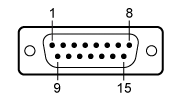
The pin descriptions shown in Tables 381A and 381B denote the typical pin assignments used by Thorlabs' family of laser diode temperature controllers and laser diode mounts. Table 381C gives the physical pin connections between the 15-pin and 9-pin sides of the CAB420-15 cable.
| Table 381A Male 15-Pin Connector | |
|---|---|
 |
|
| 1 | Status LED (+) (for TEC On/Off Indication)a |
| 2 | TEC Voltage Measurementb |
| 3 | Thermistor (-), Ground |
| 4 | Thermistor (+) |
| 5 | TEC (+) |
| 6 | TEC (+) |
| 7 | TEC (+) |
| 8 | LM 135/335 (-), Grounda |
| 9 | TEC Voltage Measurementb |
| 10 | Transducer AD 590/592 (-), LM 135/335 (+) |
| 11 | Transducer AD 590/592 (+), LM 135/335 (+) |
| 12 | No Connection |
| 13 | TEC (-), Status LED (-) |
| 14 | TEC (-), Status LED (-) |
| 15 | TEC (-), Status LED (-) |
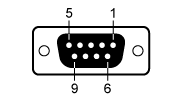
| Table 381B Female 9-Pin Connector | |
|---|---|
 |
|
| 1 | Status LED (+) (for TEC On/Off Indication)a |
| 2 | Thermistor (+) |
| 3 | Thermistor (-), Ground |
| 4 | TEC (+) |
| 5 | TEC (-), Status LED (-) |
| 6 | No Connection |
| 7 | Transducer AD 590/592 (-), LM 135/335 (+) |
| 8 | LM 135/335 (-), Grounda |
| 9 | Transducer AD 590/592 (+), LM 135/335 (+) |
| Table 381C Pin Connections | |
|---|---|
| 15-Pin Side | 9-Pin Side |
| 1 | 1 |
| 2 | 4 |
| 3 | 3 |
| 4 | 2 |
| 5 | 4 |
| 6 | 4 |
| 7 | No Connection |
| 8 | 8 |
| 9 | 5 |
| 10 | 7 |
| 11 | 9 |
| 12 | No Connection |
| 13 | 5 |
| 14 | 5 |
| 15 | No Connection |
Part Number | Description | Price | Availability |
|---|---|---|---|
CAB420-15 | Temperature Controller Cable with 15-Pin D-Sub Connector, 1.5 m | $93.43 | Today |
Recalibration Service for the TED200C Temperature Controller
Thorlabs offers a recalibration service for the TED200C Benchtop Temperature Controller. To ensure accurate measurements, we recommend recalibrating the devices every 24 months.
Requesting a Calibration
Thorlabs provides two options for requesting a calibration:
- Complete the Returns Material Authorization (RMA) form. When completing the RMA form, please enter your name, contact information, the Part #, and the Serial # of the item being returned for calibration; in the Reason for Return field, select "I would like an item to be calibrated." All other fields are optional. Once the form has been submitted, a member of our RMA team will reach out to provide an RMA Number, return instructions, and to verify billing and payment information.
- Enter the Part # and Serial # of the item that requires recalbration below and then Add to Cart. A member of our RMA team will reach out to coordinate return of the item for calibration. Should you have other items in your cart, note that the calibration request will be split off from your order for RMA processing.
Please Note: To ensure your item being returned for calibration is routed appropriately once it arrives at our facility, please do not ship it prior to being provided an RMA Number and return instructions by a member of our team.
Part Number | Description | Price | Availability |
|---|---|---|---|
CAL-TED2 | Recalibration Service for the TED200C Benchtop Temperature Controller | $209.08 | Lead Time |