 Products Home / Drivers & Mounts / Dual Current / Temperature Controllers / PRO8 Laser Diode Current & Temperature Control Modules
PRO8 Laser Diode Current & Temperature Control Modules
- Low Laser Current Noise
- Built-in Laser Diode Protection Features
- 2 Versions: Separate or Single Output Connectors
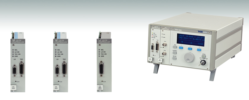
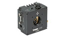
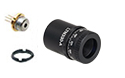
ITC8022
Module
ITC8052
Module
ITC8102DS15
Module
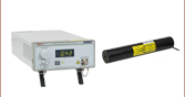
Application Idea
PRO800 Chassis with ITC8052 and PDA8000 Amplifier
(Chassis and Modules Sold Separately)


Please Wait
| Key Specificationsa | ||||
|---|---|---|---|---|
| Item # | LD Current | Max TEC Output Power |
Connector(s) | Module Width |
| ITC8022 | ±200 mA | 16 W | 9-Pin (LD), 15-Pin (TEC) |
1 Slot |
| ITC8022DS15 | 15-Pin (LD & TEC) |
|||
| ITC8052 | ±500 mA | 16 W | 9-Pin (LD), 15-Pin (TEC) |
|
| ITC8052DS15 | 15-Pin (LD & TEC) |
|||
| ITC8102 | ±1 A | 16 W | 9-Pin (LD), 15-Pin (TEC) |
|
| ITC8102DS15 | 15-Pin (LD & TEC) |
|||
| PRO8 Series Modulesa | |
|---|---|
| Laser Diode Current Controllers (Up to 8 A) | 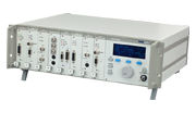 |
| TEC Temperature Controllers (Up to 64 W) | |
| Combination Laser Diode Current (Up to 1 A) & TEC Temperature Controllers (Up to 16 W) |
|
| DWDM DFB Laser Modulesb | |
| Optical Switches | |
| Photocurrent Measurement Modules | |
Features
- 3 Different Laser Current Ranges: ±200 mA, ±500 mA and ±1 A
- TEC Cooling Power: ±2 A / 16 W
- Supports All Laser and Monitor Diode Polarities (Anode Grounded / Cathode Grounded)
- Supports Constant Current (CC) and Constant Power (CP) Mode
- Low Noise and Highly Stable Operation
- Multiple Built-In Laser Diode Protection Features
- Excellent Temperature Stability (up to <0.001 °C)
- Support for Thermistor & IC Sensors
- Adjustable P, I and D-Settings of the PID Servo Loop for Optimal Temperature Settling Time
Combination Current & Temperature Control Modules
These modules are combination Laser Diode and TEC Temperature controllers designed for use with our PRO8 Series Chassis. Each module offers laser drive current ranges of 0 to ±200mA, 0 to ±500 mA, and 0 to ±1 A, along with a TEC controller that provides up to ±2 A/16 W. The PRO8 Chassis can be ordered with these modules preinstalled; contact Tech Support prior to placing your order.
The modules come in two versions: a 9-pin connector for laser current output and a 15-pin connector for TEC current output (Item # ITC8022, ITC8052, or ITC8102) or with a common 15-pin connector for both laser and TEC current output (Item # Suffix DS15). See the list to the upper right for the six options.
Thorlabs recommends recalibrating these modules every 24 months and offers a factory recalibration service. To order this service, scroll to the bottom of the page and select Item # CAL-ITC8.
Extremely Low Noise
Every module features exceptionally low laser current noise (see the Specs tab), and exceptional temperature stability better than 0.002 °C (measured with the AD590 Temperature Sensor). They also offer the same great performance independent of the mode of operation - constant current (CC), or constant power (CP).
User-Friendly Controls
The PRO8 display menu allows for the configuration of any module in the chassis. Mnemonic symbols provide user-friendly access to all operational parameters. All settings are retained in memory and automatically recalled upon powering on the mainframe as long as modules are not being moved to a different slot.
Built-In Laser Diode Protection Features
Proven laser protection features are included to safeguard sensitive laser diodes. Besides common protection functions, such as current limits, laser current soft start, and interrupt protection, an advanced circuit design ensures that AC power-line transients or power outages, as well as RF pickup, cannot affect the laser diode. Additionally, a temperature window can be set that will shut the laser down in the event the high or low thresholds of the window are exceeded.
The controllers meet the international requirements regarding laser protection (e.g. CDRH US21 CFR 1040.10). All modules include a key-operated power switch and interlock, plus many additional features.
Calibrating the Power Display
The display of the laser power can easily be calibrated with respect to the laser's monitor diode current to provide a direct optical power read-out. This is accomplished by adjusting the “CALPD” calibration constant that is accessed via the front panel soft keys or the computer interface. Please note that an optical power meter is required for this setting procedure. See our Power Meters for more details.
Setting the Temperature Control Loop
The Proportional (gain), Derivative and Integral settings of the PID control loop can each be set independently to optimize the temperature response of the system to different thermal loads.
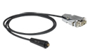
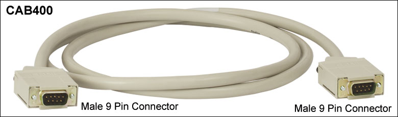
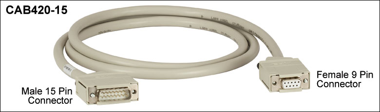
Connection Cables
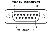
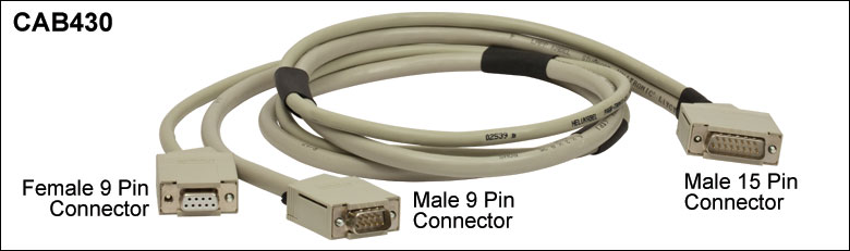
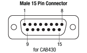
Depending on the item chosen, different cables are required to connect the modules to a Thorlabs' Laser Diode Mount. The ITC8022, ITC8052, and ITC8102, with 2 separate connectors, require the CAB400 for the laser controller and the CAB420-15 cable for the temperature controller. The ITC8022DS15, ITC8052DS15, and ITC8102DS15, with one single connector, require the CAB430 cable. The cables have to be ordered separately.
For further information, please contact Tech Support.
| Laser Diode Accessory Selection Guide | |||||
|---|---|---|---|---|---|
| Temperature Controlled Mounts | Passive Mounts | Passive Mounts with Collimation Package | Strain Relief Cables | Diode Sockets | Other Controllers |
 |
 |
 |
 |
 |
 |
| Item # | ITC8022 | ITC8052 | ITC8102 |
|---|---|---|---|
| Laser Controller: Current Control | |||
| Control Range of Injection Current | 0 to ± 200 mA | 0 to ± 500 mA | 0 to ± 1 A |
| Compliance Voltage | >5 V | ||
| Setting Resolution | 3 µA | 7.5 µA | 15 µA |
| Accuracy (Full Scale) | ±0.05 % | ±0.05% | ±0.1% |
| Noise without Ripple (10 Hz to 10 MHz, RMS, Typ.) | <2 µA | <5 µA | <10 µA |
| Ripple (50 Hz, RMS, Typ.) | <1 µA | <1 µA | <1.5 µA |
| Transients (Processor, Typ.) | <15 µA | <30 µA | <50 µA |
| Transients (Other, Typ.) | <200 µA | <500 µA | <1 mA |
| Drift (24 hrs, at Constant Ambient Temperature, Typ.) | <3 µA | <10 µA | <25 µA |
| Temperature Coefficient | <50 ppm/°C | ||
| Laser Controller: Power Control | |||
| Control Range of Photo Current | 10 µA to 2 mA | ||
| Reverse Bias Voltage | 0 to 10 V (adjustable) | ||
| Resolution Photo Current | 30 nA | ||
| Accuracy (Typ.) | ±0.1% | ||
| Laser Controller: Current Limit | |||
| Setting Range | 0 to ≥ 200 mA | 0 to ≥ 500 mA | 0 to ≥ 1 A |
| Resolution | 6 µA | 15 µA | 30 µA |
| Accuracy | ±200 µA | ±500 µA | ±2 mA |
| Laser Voltage Measurement | |||
| Measurement Principle | 4-Wire (improves accuracy by compensating for cable resistance) | ||
| Measurement Range | 0 to 10 V | ||
| Resolution | 0.3 mV | ||
| Accuracy | ±5 mV | ||
| Temperature Controller: Output | |||
| Control Range of TEC Current | -2 A to +2 A | ||
| Compliance Voltage | >8 V | ||
| Maximum Output Power | 16 W | ||
| Measurement resolution of TEC Current | 0.07 mA | ||
| Measurement resolution of TEC Voltage | 0.3 mV | ||
| Noise and Ripple Typ. | <1 mA | ||
| Temperature Controller: Current Limit | |||
| Setting Range (20-Turn Pot) | 0 to ≥2 A | ||
| Resolution | 0.5 mA | ||
| Setting Accuracy | ±20 mA | ||
| Temperature Controller: Sensor Data | |||
| Thermistor | |||
| Control Range | 200 Ω to 40 kΩ (10 kΩ norminal resistance at 25 °C) | ||
| Resolution | 0.7 Ω | ||
| Accuracy | ±10 Ω | ||
| Stability (24 hrs) | <1 Ω | ||
| AD590, AD592, & LM335 | |||
| Control Range | -12.375 to +90 °C | ||
| Resolution | 0.0015 °C | ||
| Accuracy | ±0.1 °C | ||
| Temperature Stability (Typ.) | <0.001 °C | ||
| General Data | |||
| Width | 1 PRO8 Slot | ||
| LD/TEC-Connector | 9-pin (LD)/15-pin (TE) D-Sub (ITC8000); Common 15-pin D-Sub (ITC8000DS15) | ||
| Operating Temperature | 0 to 40 °C | ||
| Storage Temperature | -40 to +70 °C | ||
All Data Valid at 23 ± 5 °C and 45 ± 15% Rel. Humidity
ITC8XXX Laser Diode Contoller
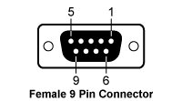
| Pin | Connection | Pin | Connection |
|---|---|---|---|
| 1 | Output for Interlock and Status LASER ON/OFF | 6 | Laser Diode Cathode Measurement Input for Laser Diode Voltage) |
| 2 | Monitor Diode Ground | 7 | Laser Diode Cathode (with Polarity AG) |
| 3 | Laser Diode Ground | 8 | Laser Diode Anode (with Polarity CG) |
| 4 | Monitor Diode Input | ||
| 5 | Pin 1 Ground | 9 | Laser Diode Anode (Measurement Input for Laser Diode Voltage) |
ITC8XXX TEC Connection

| Pin | Connection | Pin | Connection |
|---|---|---|---|
| 1 | Status-LED Anode | 9 | Not Connected |
| 2 | Not Connected | 10 | AD590 (-) (PT100 for TC8xxxPT) |
| 3 | Thermistor Ground (-) | 11 | AD590 (+) (PT100 for TC8xxxPT) |
| 4 | Thermistor (+) | ||
| 5 | TEC Element (+) | 12 | Not Connected |
| 6 | TEC Element (+) | 13 | TEC Element Ground (-) |
| 7 | Not Connected | 14 | TEC Element Ground (-) |
| 8 | Status LED Cathode (Ground) |
15 | TEC Element Ground (-) |
*Connect the TEC element and the temperature sensor with shielded cables to the TEC connector. The shielding of the cables must be connected to ground (pins 13, 14, 15).
ITC8XXXDS15 LD/TED Connection
| Pin | Connection | Pin | Connection |
|---|---|---|---|
| 1 | Interlock | 9 | Laser Diode Cathode (Measurement Input for Laser Diode Voltage) |
| 2 | Monitor Diode Ground | 10 | Laser diode cathode (polarity AG) |
| 3 | Laser Diode Ground | 11 | Laser diode anode (polarity CG) |
| 4 | Monitor Diode Anode or Cathode / Bias | 12 | Laser Diode Anode (Measurement Input for Laser Diode Voltage) |
| 5 | Interlock Ground | ||
| 6 | AD 590 (+) | 13 | AD 590 (-) |
| 7 | TEC (+) | 14 | Thermistor Ground |
| 8 | TEC (-) (ground) | 15 | Thermistor |
The following parts are included together with each of our ITC8000 Series Current & Temperature Controllers:
- ITC8000 Series Current & Temperature Controller Module
- Operating Manual
PID Basics
The PID circuit is often utilized as a control loop feedback controller and is very commonly used for many forms of servo circuits. The letters making up the acronym PID correspond to Proportional (P), Integral (I), and Derivative (D), which represents the three control settings of a PID circuit. The purpose of any servo circuit is to hold the system at a predetermined value (set point) for long periods of time. The PID circuit actively controls the system so as to hold it at the set point by generating an error signal that is essentially the difference between the set point and the current value. The three controls relate to the time-dependent error signal; at its simplest, this can be thought of as follows: Proportional is dependent upon the present error, Integral is dependent upon the accumulation of past error, and Derivative is the prediction of future error. The results of each of the controls are then fed into a weighted sum, which then adjusts the output of the circuit, u(t). This output is fed into a control device, its value is fed back into the circuit, and the process is allowed to actively stabilize the circuit’s output to reach and hold at the set point value. The block diagram below illustrates very simply the action of a PID circuit. One or more of the controls can be utilized in any servo circuit depending on system demand and requirement (i.e., P, I, PI, PD, or PID).
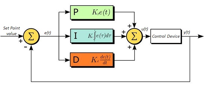
Through proper setting of the controls in a PID circuit, relatively quick response with minimal overshoot (passing the set point value) and ringing (oscillation about the set point value) can be achieved. Let’s take as an example a temperature servo, such as that for temperature stabilization of a laser diode. The PID circuit will ultimately servo the current to a Thermo Electric Cooler (TEC) (often times through control of the gate voltage on an FET). Under this example, the current is referred to as the Manipulated Variable (MV). A thermistor is used to monitor the temperature of the laser diode, and the voltage over the thermistor is used as the Process Variable (PV). The Set Point (SP) voltage is set to correspond to the desired temperature. The error signal, e(t), is then just the difference between the SP and PV. A PID controller will generate the error signal and then change the MV to reach the desired result. If, for instance, e(t) states that the laser diode is too hot, the circuit will allow more current to flow through the TEC (proportional control). Since proportional control is proportional to e(t), it may not cool the laser diode quickly enough. In that event, the circuit will further increase the amount of current through the TEC (integral control) by looking at the previous errors and adjusting the output in order to reach the desired value. As the SP is reached [e(t) approaches zero], the circuit will decrease the current through the TEC in anticipation of reaching the SP (derivative control).
Please note that a PID circuit will not guarantee optimal control. Improper setting of the PID controls can cause the circuit to oscillate significantly and lead to instability in control. It is up to the user to properly adjust the PID gains to ensure proper performance.
PID Theory
The output of the PID control circuit, u(t), is given as
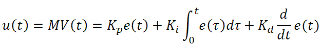
where
Kp= Proportional Gain
Ki = Integral Gain
Kd = Derivative Gain
e(t) = SP - PV(t)
From here we can define the control units through their mathematical definition and discuss each in a little more detail. Proportional control is proportional to the error signal; as such, it is a direct response to the error signal generated by the circuit:
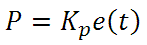
Larger proportional gain results is larger changes in response to the error, and thus affects the speed at which the controller can respond to changes in the system. While a high proportional gain can cause a circuit to respond swiftly, too high a value can cause oscillations about the SP value. Too low a value and the circuit cannot efficiently respond to changes in the system.
Integral control goes a step further than proportional gain, as it is proportional to not just the magnitude of the error signal but also the duration of the error.
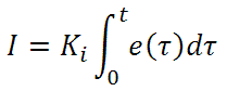
Integral control is highly effective at increasing the response time of a circuit along with eliminating the steady-state error associated with purely proportional control. In essence integral control sums over the previous error, which was not corrected, and then multiplies that error by Ki to produce the integral response. Thus, for even small sustained error, a large aggregated integral response can be realized. However, due to the fast response of integral control, high gain values can cause significant overshoot of the SP value and lead to oscillation and instability. Too low and the circuit will be significantly slower in responding to changes in the system.
Derivative control attempts to reduce the overshoot and ringing potential from proportional and integral control. It determines how quickly the circuit is changing over time (by looking at the derivative of the error signal) and multiplies it by Kd to produce the derivative response.

Unlike proportional and integral control, derivative control will slow the response of the circuit. In doing so, it is able to partially compensate for the overshoot as well as damp out any oscillations caused by integral and proportional control. High gain values cause the circuit to respond very slowly and can leave one susceptible to noise and high frequency oscillation (as the circuit becomes too slow to respond quickly). Too low and the circuit is prone to overshooting the SP value. However, in some cases overshooting the SP value by any significant amount must be avoided and thus a higher derivative gain (along with lower proportional gain) can be used. The chart below explains the effects of increasing the gain of any one of the parameters independently.
| Parameter Increased | Rise Time | Overshoot | Settling Time | Steady-State Error | Stability |
|---|---|---|---|---|---|
| Kp | Decrease | Increase | Small Change | Decrease | Degrade |
| Ki | Decrease | Increase | Increase | Decrease Significantly | Degrade |
| Kd | Minor Decrease | Minor Decrease | Minor Decrease | No Effect | Improve (for small Kd) |
Tuning
In general the gains of P, I, and D will need to be adjusted by the user in order to best servo the system. While there is not a static set of rules for what the values should be for any specific system, following the general procedures should help in tuning a circuit to match one’s system and environment. In general a PID circuit will typically overshoot the SP value slightly and then quickly damp out to reach the SP value.
Manual tuning of the gain settings is the simplest method for setting the PID controls. However, this procedure is done actively (the PID controller turned on and properly attached to the system) and requires some amount of experience to fully integrate. To tune your PID controller manually, first the integral and derivative gains are set to zero. Increase the proportional gain until you observe oscillation in the output. Your proportional gain should then be set to roughly half this value. After the proportional gain is set, increase the integral gain until any offset is corrected for on a time scale appropriate for your system. If you increase this gain too much, you will observe significant overshoot of the SP value and instability in the circuit. Once the integral gain is set, the derivative gain can then be increased. Derivative gain will reduce overshoot and damp the system quickly to the SP value. If you increase the derivative gain too much, you will see large overshoot (due to the circuit being too slow to respond). By playing with the gain settings, you can maximize the performance of your PID circuit, resulting in a circuit that quickly responds to changes in the system and effectively damps out oscillation about the SP value.
| Control Type | Kp | Ki | Kd |
|---|---|---|---|
| P | 0.50 Ku | - | - |
| PI | 0.45 Ku | 1.2 Kp/Pu | - |
| PID | 0.60 Ku | 2 Kp/Pu | KpPu/8 |
While manual tuning can be very effective at setting a PID circuit for your specific system, it does require some amount of experience and understanding of PID circuits and response. The Ziegler-Nichols method for PID tuning offers a bit more structured guide to setting PID values. Again, you’ll want to set the integral and derivative gain to zero. Increase the proportional gain until the circuit starts to oscillate. We will call this gain level Ku. The oscillation will have a period of Pu. Gains are for various control circuits are then given below in the chart.
| Posted Comments: | |
pedrueze
(posted 2015-11-04 13:01:27.1) Dear all,
I have a controller (ITC8052 module in a rack Profile PRO 8000), a cable type SR9-DB9 to use with a L9805E2P5 laser diode. As I read the manual of the module, it is not clear to me which are the parameters that I have to control in order to get the diode laser running. For example (if I see the speecsheet of this laser diode), it is not clear which are the parameters that I have to change for control:
Operating volage
LD reverse voltage
PD reverse voltage
Operating voltage
I see the following parameters in the display (pag 30 in the manual):
For the current:
I LD
I max
I lim (I think this is the one that is controller by the screw, right?)
I PD
For the voltage:
U LD
U bia
seems to be the ones that I have to operate, but i am not sure.
Another problem is the diverse current parameters:
Ilim is supposed to be the 120 mA for my laser, so I have to change this with a scredriver in the fron panel (that "brown box"?) until which point? How can I see the change in the current limit when I manipulate the screw?
My intention is to switch on the laser and change the optical power by changing the power. I am not currently using a TEC so I will work at low powers. As long I have a photodiode in my laser diode, both manual and specsheet are poor self-explained on how to make it work and not burn it.
Any help is very welcome.
Kind regards shallwig
(posted 2015-11-05 05:17:04.0) This is a response from Stefan at Thorlabs. Thank you very much for your inquiry. Before running the laser diode it is important to check the laser diodes limits and its polarity. You can find these information in the spec sheet of the diode here: http://www.thorlabs.com/thorcat/6100/L9805E2P5-SpecSheet.pdf
The polarity of the laser diode is anode grounded (AG). The photodiode has polarity cathode grounded (CG). The typical operating current is at 95mA while the maximum rating is 120mA. For the operating voltage the maximum is given with 1.7V. To avoid damaging the diode by not proper heat dissipation/ sufficient cooling we recommend to use a TEC element here.
By inserting the diode in one of our mounts and using the appropriate cables you make sure the wiring is done correctly.
Then you can follow the instruction in the manual from page 13 http://www.thorlabs.de/thorcat/7500/ITC8052-Manual.pdf
First it is important to set the hardware limit current I_LIM: the laser diode current is set with the potentiometer marked I_LIM at the front panel of the ITC8. The value is displayed continually in the channel menu of the module so you can watch it during adjustment. I_Max denotes the software limit and can be changed in the channel menu. The software Limitn I_Max has same protective function as the Hardware limit I_Lim. The lower of the two limits will limit the laser diode current.
If you are not using a mount from us please check the Pin Assignment of the LD connector as shown on page 16.
How to use the operation menu of the PRO8 is described from page 27.
You can choose between two modes, constant current or constant power. In first mode you set a laser diode current I_LD while in constant power you can control the output via monitor photodiode which is built in the laser diode.
In the menu only three parameters can be shown at the same time for setting all other parameters please use the scroll functions. You can find a list of all parameters also in the manual on page 30.
The monitor diode input can be operated without or with bias voltage (0 V...10 V). The polarity for the monitor diode must be set accordingly. A calibration of the monitor diode is described on page 32 in the manual.
I will contact you directly to check if you need any further assistance to run your laser diode. adan
(posted 2015-05-01 18:18:20.073) Could you please tell us if the ITC8102 MODULE (PRICE $2160) include the following items:
1.- PRO800 chassis
2.- TEC CONTROLLER
Like apear in the page of PRO8 LASER DIODE CURRENT & TEMPERATURE CONYTOL MODULES OF YOUR CATALOG. shallwig
(posted 2015-05-04 05:35:11.0) This is a response from Stefan at Thorlabs. Thank you very much for your inquiry. The ITC80102 Module contains a current and TEC controller but the PRO8 chassis in which you have to build in this card is not included at this price you mentioned. The different PRO8 systems can be found on our website here: http://www.thorlabs.de/newgrouppage9.cfm?objectgroup_id=895&pn=PRO800
We will contact you directly to discuss your needs in detail. |

 Zoom
Zoom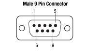 | |
Pin Connections |
| 1 | Interlock and Status LASER ON/OFF |
| 2 | Photodiode |
| 3 | Laser Diode Ground |
| 4 | Photodiode |
| 5 | Ground for Pin 1 |
| 6 | Voltage Measurement Laser Diode Cathode |
| 7 | Laser Diode Cathode (with Polarity Anode Grounded - AG) |
| 8 | Laser Diode Anode (with Polarity Cathode Grounded - CG) |
| 9 | Voltage Measurement Laser Diode Anode |

 Zoom
Zoom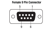 | |
Pin Connections |
| 1 | Status LED (+) (for TEC ON/OFF indication), CAB430: N.C. |
| 2 | Thermistor (+) |
| 3 | Thermistor (-), Ground |
| 4 | TEC (+) |
| 5 | TEC (-), Status LED (-) |
| 6 | N.C. |
| 7 | Transducer AD 590/592 (-), LM 135/335 (+) |
| 8 | N.C. |
| 9 | Transducer AD 590/592 (+), LM 135/335 (+) |
 | |
Pin Connections |
| 1 | Status LED (+) (for TEC ON/OFF indication) |
| 2 | N.C. |
| 3 | Thermistor (-), Ground |
| 4 | Thermistor (+) |
| 5 | TEC (+) |
| 6 | TEC (+) |
| 7 | TEC (+) |
| 8 | LM 135/335 (-), Ground |
| 9 | N.C. |
| 10 | Transducer AD 590/592 (-), LM 135/335 (+) |
| 11 | Transducer AD 590/592 (+), LM 135/335 (+) |
| 12 | N.C. |
| 13 | TEC (-), Status LED (-) |
| 14 | TEC (-), Status LED (-) |
| 15 | TEC (-), Status LED (-) |

 Zoom
Zoom | |
Pin Connections |
| 1 | Interlock and Status LASER ON/OFF |
| 2 | Photodiode |
| 3 | Laser Diode Ground |
| 4 | Photodiode |
| 5 | Ground for Pin 1 |
| 6 | Voltage Measurement Laser Diode Cathode |
| 7 | Laser Diode Cathode (with Polarity Anode Grounded - AG) |
| 8 | Laser Diode Anode (with Polarity Cathode Grounded - CG) |
| 9 | Voltage Measurement Laser Diode Anode |
| |
Pin Connections |
| 1 | Status LED (+) (for TEC ON/OFF indication), CAB430: N.C. |
| 2 | Thermistor (+) |
| 3 | Thermistor (-), Ground |
| 4 | TEC (+) |
| 5 | TEC (-), Status LED (-) |
| 6 | N.C. |
| 7 | Transducer AD 590/592 (-), LM 135/335 (+) |
| 8 | N.C. |
| 9 | Transducer AD 590/592 (+), LM 135/335 (+) |
 | |
Pin Connections |
| 1 | Interlock and Status LASER ON/OFF |
| 2 | Photodiode |
| 3 | Laser Diode Ground |
| 4 | Photodiode |
| 5 | Ground for Pin 1 |
| 6 | Transducer AD 590/592 (+), LM 135/335 (+) |
| 7 | TEC (+) |
| 8 | TEC (-) |
| 9 | Voltage Measurement Laser Diode Cathode |
| 10 | Laser Diode Cathode (with Polarity Anode Grounded - AG) |
| 11 | Laser Diode Anode (with Polarity Cathode Grounded - CG) |
| 12 | Voltage Measurement Laser Diode Anode |
| 13 | Transducer AD 590/592 (-), LM 135/335 (+) |
| 14 | Thermistor (-), Ground |
| 15 | Thermistor (+) |
| Calibration Service Item # | Compatible Modules |
|---|---|
| CAL-ITC8 | ITC8022, ITC8022DS15, ITC8052, ITC8052DS15, ITC8102, ITC8102DS15 |
Thorlabs offers recalibration service for our ITC8000 Series Laser Diode Current & TEC Control Modules. To ensure accurate measurements, we recommend recalibrating the devices every 24 months. The table to the right lists the modules for which the CAL-ITC8 recalibration service is available.
Requesting a Calibration
Thorlabs provides two options for requesting a calibration:
- Complete the Returns Material Authorization (RMA) form. When completing the RMA form, please enter your name, contact information, the Part #, and the Serial # of the item being returned for calibration; in the Reason for Return field, select "I would like an item to be calibrated." All other fields are optional. Once the form has been submitted, a member of our RMA team will reach out to provide an RMA Number, return instructions, and to verify billing and payment information.
- Enter the Part # and Serial # of the item that requires recalibration below and then Add to Cart. A member of our RMA team will reach out to coordinate return of the item for calibration. Should you have other items in your cart, note that the calibration request will be split off from your order for RMA processing.
Please Note: To ensure your item being returned for calibration is routed appropriately once it arrives at our facility, please do not ship it prior to being provided an RMA Number and return instructions by a member of our team.