 Products Home
High-Speed Free-Space Detectors
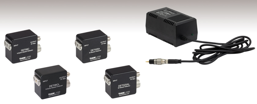
- Sensitive to Wavelengths from 400 - 1700 nm
- Bandwidths from 2 GHz to 5 GHz
- Rise Times as Short as 70 ps
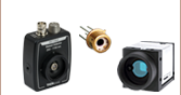
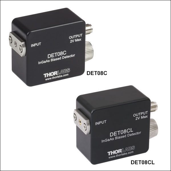
DET08C
AR-Coated Window
DET08CL
Uncoated Ball Lens
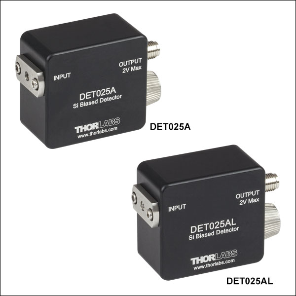
DET025A
AR-Coated Window
DET025AL
Uncoated Ball Lens
DET2B
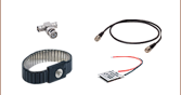
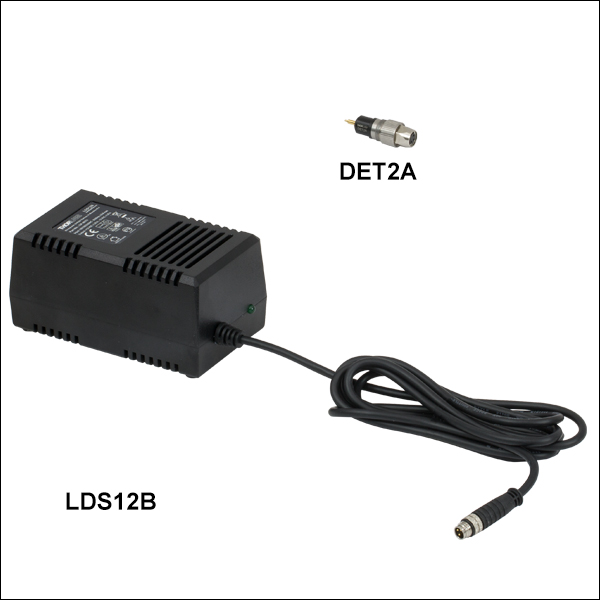
Replaces the battery in our DET series detectors and includes the LDS12B power supply and DET2A power adapter, shown connected.


Please Wait
| Selection Guide for High-Speed Free-Space Detectors | ||||
|---|---|---|---|---|
| Wavelength | Element | Input | Bandwidth | Model |
| 400 - 1100 nm | Si | Window | 2 GHz | DET025A |
| Lens | DET025AL | |||
| 800 - 1700 nm | InGaAs | Window | 5 GHz | DET08C |
| Lens | DET08CL | |||

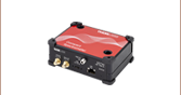
Click to Enlarge
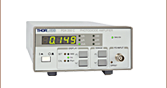
PDA200C Benchtop Photodiode Amplifier Connected to a DET025A Photodetector Using an SMA-to-BNC Cable
Features
- Four Models Cover Wavelengths from 400 - 1700 nm
- Bandwidths Ranging from 2 to 5 GHz
- Rise Times from 70 ps to 155 ps
- Free-Space Input
- Available with a Flat, AR-Coated Window or Uncoated N-BK7 Ball Lens
- SMA Output Connector
- 8-32 (M4) Tap for Post Mounting
Thorlabs offers a variety of high-speed, high-bandwidth photodetectors designed for free-space input. Together, these detectors are sensitive from the visible to the near infrared (400 - 1700 nm); please see the "Selection Guide" table above for the exact spectral range covered by each detector. All detectors shown here feature GHz signal bandwidths and offer the same ease of use as the rest of our popular DET series. These detectors are designed to perform in test or measurement applications, including research in the fields of data communications, analog microwave, and general high-speed photonics. For comparable detection of fiber-coupled radiation, Thorlabs offers high-speed fiber-coupled detectors. We also have a variety of internally biased free-space photodiodes that operate at slower speeds than the detectors featured here. Our biased photodetectors are compatible with our benchtop photodiode amplifier and PMT transimpedance amplifier.
These free-space detectors are reverse biased and contain an internal bias battery, producing a linear response to the incident input light. To maintain the high signal bandwidth, the signal is output through an SMA connector. Thorlabs offers a complete range of electrical adapters and cables, including SMA cables and SMA-to-BNC adapters, for monitoring the output signal with an oscilloscope or other measurement electronics.
Our Si-based free-space detectors are designed for use in the 400 - 1100 nm (DET025A and DET025AL) wavelength range and provide a bandwidth of 2 GHz. For applications extending into the near infrared, consider our InGaAs-based free-space detectors, which provide detection in the 800 - 1700 nm (DET08C and DET08CL) wavelength range and provide a bandwidth of 5 GHz. When looking at high-speed signals, Thorlabs recommends using a 50 Ω load resistor. For lower bandwidth applications, our variable terminator or fixed stub-style terminators quickly adjusts the measured voltage.
Click to Enlarge
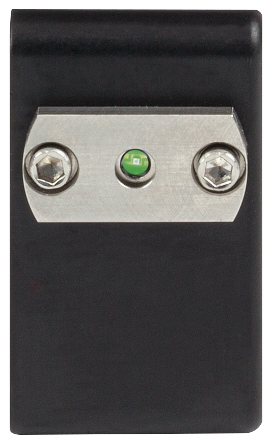
Uncoated Ball Lens Input on the DET08CL
Click to Enlarge
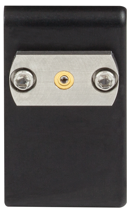
Flat, AR-Coated Window Input on the DET025A
Both of the Si-based and InGaAs-based detectors are available with either a flat, AR-coated window or an uncoated ball lens free-space input (see the photos to the right for details). The ball lens captures and focuses incident light onto the relatively small active area of the detector, making it advantagous for use in applications where the signal input needs to be increased. If the input signal is sufficiently large, a detector with a window over the aperture is recommended since focusing a strong input signal can cause saturation, and possibly damage, to the detector. Additionally, we recommend the detectors with the window over those with the lens when working with a pulsed source, as the chromatic dispersion that occurs as the light passes through the lens can artificially elongate the pulse.
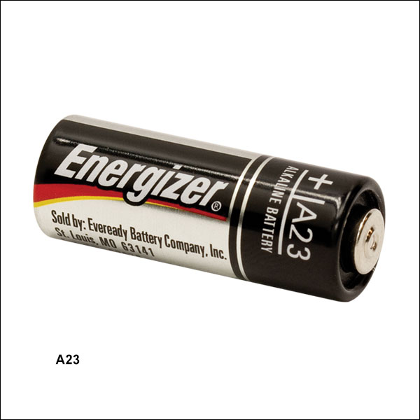
All of these detectors include an A23 12 VDC Bias battery; this was chosen because it provides an extremely low noise source of power. This battery is optionally replaceable by the DET2B Power Adapter Bundle (sold below) when the detector is being used in applications where a small increase in the signal noise due to noise in the line voltage is permissible or the finite lifetime of a battery is not acceptable. Please note that due to slight physical variations of the positive terminal from manufacturer to manufacturer, Thorlabs only recommends using an Energizer® battery in our DET series of photodetectors.
Please note that inhomogeneities at the edges of the active area of the detector can generate unwanted capacitance and resistance effects that distort the time-domain response of the photodiode output. Thorlabs therefore recommends that the incident light on the photodiode is well centered on the active area. Mounting a focusing lens or pinhole in front of the detector element is recommended.
| Item # | DET025A | DET025AL | DET08C | DET08CL |
|---|---|---|---|---|
| Wavelength Range | 400 - 1100 nm | 800 - 1700 nm | ||
| Material | Si | InGaAs | ||
| Active Area | Ø250 µm | Ø80 µm | ||
| Bandwidth (-3 dB)a,b,c | 2 GHz | 5 GHz | ||
| Input | Flat, AR-Coated Window | Uncoated N-BK7 Ball Lens | Flat, AR-Coated Window | Uncoated N-BK7 Ball Lens |
| Ball Lens Diameter | N/A | 0.059" (1.50 mm) | N/A | 0.059" (1.50 mm) |
| Aperture Size | Ø0.13" (Ø3.2 mm) | Ø0.13" (Ø3.2 mm) | ||
| Signal Output | SMA | SMA | ||
| Minimum Resistor Load | 50 Ω | 50 Ω | ||
| Maximum Peak Power | 18 mW | 100 mW | ||
| Output Voltaged | 2 V (Max) | |||
| Rise Time (tr) | 150 ps @ 653 nm, 20%/80%a,b,c (Typ.) | 70 ps @ 952 nm, 20%/80%a,b,c (Typ.) | ||
| Fall Time (tf) | 150 ps @ 653 nm, 80%/20%a,b,c (Typ.) | 110 ps @ 952 nm, 80%/20%a,b,c (Typ.) | ||
| Bias Voltage | 12 V | |||
| Dark Currenta,e | 35 pA | 1.5 nA | ||
| NEP (Maximum) | 9.29 x 10⁻¹⁵ W/√Hz (@ 730 nm) | 2 x 10-15 W/√Hz (@ 1550 nm) | ||
| Junction Capacitance | 1.73 pF (Max) | 0.3 pF | ||
| Photodiode Element | - | FDS025 | - | |
Note: The data for all graphs above were obtained for their respective detectors with the AR-Coated windows included in the measurement set up.
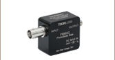
Signal Output
SMA Female
0 - 10 V w/ 50 Ω
Battery Lifetime
When using a battery-operated photodetector it is important to understand the battery’s lifetime and how this affects the operation of the detector. As a current output device, the output current of the photodetector is directly proportional to the light incidented on the detector. Most users will convert this current to a voltage by using a load-terminating resistor. The resistance value is approximately equal to the circuit gain. For very high speed detectors, such as those sold on this page, it is very important to use a 50 Ω terminating resistor to match the impedance of standard coax cables to reduce cable reflections and improve overall signal performance and integrity. Most high bandwidth scopes come equipped with this termination.
The battery usage lifetime directly correlates to the current used by the detector. Most battery manufacturers provide a battery lifetime in terms of mA hr. For example, the battery supplied with the DET08CL detectors is rated for 40 mA hrs. This means that it will reliably operate for 40 hr at a current draw of 1.0 mA. This battery will be used in the following example on how to determine battery lifetime based on usage.
For this example we have a 780 nm light source with an average 1 mW power is applied to an DET08CL. The responsivity of a biased photodetector based on the response curve at this wavelength is 0.5 A/W. The photocurrent can be calculated as:
Given the battery has a rated lifetime of 40 mA hr, the battery will last:
or 3.3 days of continuous use. By reducing the average incident power of the light to 10 µW, the same battery would last for about 333 days when used continuously. When using the recommended 50 Ω terminating load, the 0.5 mA photocurrent will be converted into a voltage of:
If the incident power level is reduced to 10 µW, the output voltage becomes 0.25 mV. For some measurement devices this signal level may be too low and a compromise between battery life and measurement accuracy will need to be made.
When using a battery-powered, biased photodetector, it is desirable to use as low a light intensity as is possible, keeping in mind the minimum voltage levels required. It is also important to remember that a battery will not immediately cease producing a current as it nears the end of its lifetime. Instead, the voltage of the battery will drop, and the electric potential being applied to the photodiode will decrease. This in turn will increase the response time of the detector and lower its bandwidth. As a result, it is important to make sure the battery has sufficient voltage (as given in the Troubleshooting chapter of the detector's manual) for the detector to operate within its specified parameters. The voltage can be checked with a multimeter.
Another suggestion to increase the battery lifetime is to remove, or power down the light source illuminating the sensor. Without the light source, the photodetector will continue to draw current proportional to the photodetector’s dark current, but this current will be significantly smaller. For example, the DET08CL has a dark current less than 1.5 nA.
For applications where a DET series photodetector is being continuously illuminated with a relatively high-power light source or if having to change the battery is not acceptable, we offer the DET2B power adapter bundle, which includes the power adapter and power supply (sold below). The drawback to this option is the noise in the line voltage will add to the noise in the output signal and could cause more measurement uncertainty.
Photodiode Tutorial
Theory of Operation
A junction photodiode is an intrinsic device that behaves similarly to an ordinary signal diode, but it generates a photocurrent when light is absorbed in the depleted region of the junction semiconductor. A photodiode is a fast, highly linear device that exhibits high quantum efficiency and may be used in a variety of different applications.
It is necessary to be able to correctly determine the level of the output current to expect and the responsivity based upon the incident light. Depicted in Figure 1 is a junction photodiode model with basic discrete components to help visualize the main characteristics and gain a better understanding of the operation of Thorlabs' photodiodes.
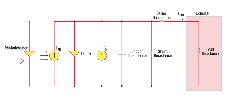
Figure 1: Photodiode Model
Photodiode Terminology
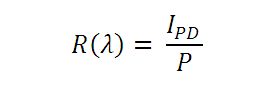
Responsivity
The responsivity of a photodiode can be defined as a ratio of generated photocurrent (IPD) to the incident light power (P) at a given wavelength:
Modes of Operation (Photoconductive vs. Photovoltaic)
A photodiode can be operated in one of two modes: photoconductive (reverse bias) or photovoltaic (zero-bias). Mode selection depends upon the application's speed requirements and the amount of tolerable dark current (leakage current).
Photoconductive
In photoconductive mode, an external reverse bias is applied, which is the basis for our DET series detectors. The current measured through the circuit indicates illumination of the device; the measured output current is linearly proportional to the input optical power. Applying a reverse bias increases the width of the depletion junction producing an increased responsivity with a decrease in junction capacitance and produces a very linear response. Operating under these conditions does tend to produce a larger dark current, but this can be limited based upon the photodiode material. (Note: Our DET detectors are reverse biased and cannot be operated under a forward bias.)
Photovoltaic
In photovoltaic mode the photodiode is zero biased. The flow of current out of the device is restricted and a voltage builds up. This mode of operation exploits the photovoltaic effect, which is the basis for solar cells. The amount of dark current is kept at a minimum when operating in photovoltaic mode.
Dark Current
Dark current is leakage current that flows when a bias voltage is applied to a photodiode. When operating in a photoconductive mode, there tends to be a higher dark current that varies directly with temperature. Dark current approximately doubles for every 10 °C increase in temperature, and shunt resistance tends to double for every 6 °C rise. Of course, applying a higher bias will decrease the junction capacitance but will increase the amount of dark current present.
The dark current present is also affected by the photodiode material and the size of the active area. Silicon devices generally produce low dark current compared to germanium devices which have high dark currents. The table below lists several photodiode materials and their relative dark currents, speeds, sensitivity, and costs.
| Material | Dark Current | Speed | Spectral Range | Cost |
|---|---|---|---|---|
| Silicon (Si) | Low | High Speed | Visible to NIR | Low |
| Germanium (Ge) | High | Low Speed | NIR | Low |
| Gallium Phosphide (GaP) | Low | High Speed | UV to Visible | Moderate |
| Indium Gallium Arsenide (InGaAs) | Low | High Speed | NIR | Moderate |
| Indium Arsenide Antimonide (InAsSb) | High | Low Speed | NIR to MIR | High |
| Extended Range Indium Gallium Arsenide (InGaAs) | High | High Speed | NIR | High |
| Mercury Cadmium Telluride (MCT, HgCdTe) | High | Low Speed | NIR to MIR | High |
Junction Capacitance
Junction capacitance (Cj) is an important property of a photodiode as this can have a profound impact on the photodiode's bandwidth and response. It should be noted that larger diode areas encompass a greater junction volume with increased charge capacity. In a reverse bias application, the depletion width of the junction is increased, thus effectively reducing the junction capacitance and increasing the response speed.
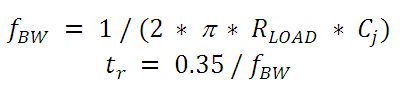
Bandwidth and Response
A load resistor will react with the photodetector junction capacitance to limit the bandwidth. For best frequency response, a 50 Ω terminator should be used in conjunction with a 50 Ω coaxial cable. The bandwidth (fBW) and the rise time response (tr) can be approximated using the junction capacitance (Cj) and the load resistance (RLOAD):
Noise Equivalent Power
The noise equivalent power (NEP) is the generated RMS signal voltage generated when the signal to noise ratio is equal to one. This is useful, as the NEP determines the ability of the detector to detect low level light. In general, the NEP increases with the active area of the detector and is given by the following equation:
Here, S/N is the Signal to Noise Ratio, Δf is the Noise Bandwidth, and Incident Energy has units of W/cm2. For more information on NEP, please see Thorlabs' Noise Equivalent Power White Paper.
Terminating Resistance
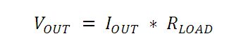
A load resistance is used to convert the generated photocurrent into a voltage (VOUT) for viewing on an oscilloscope:
Depending on the type of the photodiode, load resistance can affect the response speed. For maximum bandwidth, we recommend using a 50 Ω coaxial cable with a 50 Ω terminating resistor at the opposite end of the cable. This will minimize ringing by matching the cable with its characteristic impedance. If bandwidth is not important, you may increase the amount of voltage for a given light level by increasing RLOAD. In an unmatched termination, the length of the coaxial cable can have a profound impact on the response, so it is recommended to keep the cable as short as possible.
Shunt Resistance
Shunt resistance represents the resistance of the zero-biased photodiode junction. An ideal photodiode will have an infinite shunt resistance, but actual values may range from the order of ten Ω to thousands of MΩ and is dependent on the photodiode material. For example, and InGaAs detector has a shunt resistance on the order of 10 MΩ while a Ge detector is in the kΩ range. This can significantly impact the noise current on the photodiode. For most applications, however, the high resistance produces little effect and can be ignored.
Series Resistance
Series resistance is the resistance of the semiconductor material, and this low resistance can generally be ignored. The series resistance arises from the contacts and the wire bonds of the photodiode and is used to mainly determine the linearity of the photodiode under zero bias conditions.
Common Operating Circuits
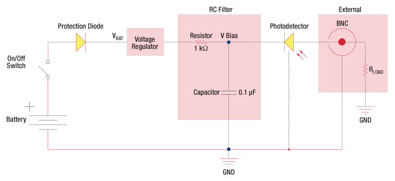
Figure 2: Reverse-Biased Circuit (DET Series Detectors)
The DET series detectors are modeled with the circuit depicted above. The detector is reverse biased to produce a linear response to the applied input light. The amount of photocurrent generated is based upon the incident light and wavelength and can be viewed on an oscilloscope by attaching a load resistance on the output. The function of the RC filter is to filter any high-frequency noise from the input supply that may contribute to a noisy output.
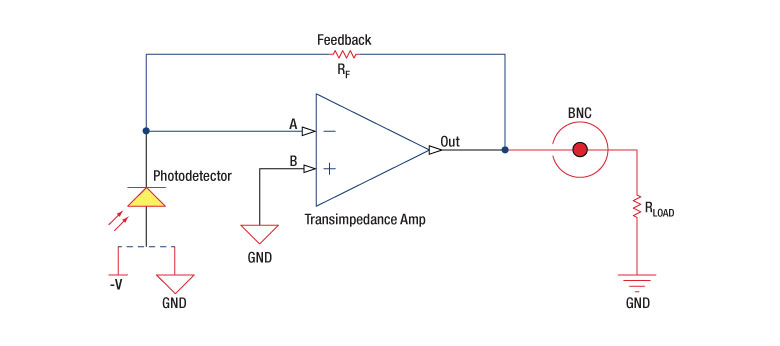
Figure 3: Amplified Detector Circuit
One can also use a photodetector with an amplifier for the purpose of achieving high gain. The user can choose whether to operate in Photovoltaic of Photoconductive modes. There are a few benefits of choosing this active circuit:
- Photovoltaic mode: The circuit is held at zero volts across the photodiode, since point A is held at the same potential as point B by the operational amplifier. This eliminates the possibility of dark current.
- Photoconductive mode: The photodiode is reversed biased, thus improving the bandwidth while lowering the junction capacitance. The gain of the detector is dependent on the feedback element (Rf). The bandwidth of the detector can be calculated using the following:
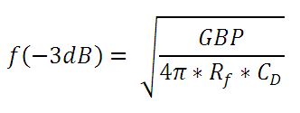
where GBP is the amplifier gain bandwidth product and CD is the sum of the junction capacitance and amplifier capacitance.
Effects of Chopping Frequency
The photoconductor signal will remain constant up to the time constant response limit. Many detectors, including PbS, PbSe, HgCdTe (MCT), and InAsSb, have a typical 1/f noise spectrum (i.e., the noise decreases as chopping frequency increases), which has a profound impact on the time constant at lower frequencies.
The detector will exhibit lower responsivity at lower chopping frequencies. Frequency response and detectivity are maximized for
![]()
Pulsed Laser Emission: Power and Energy Calculations

Determining whether emission from a pulsed laser is compatible with a device or application can require referencing parameters that are not supplied by the laser's manufacturer. When this is the case, the necessary parameters can typically be calculated from the available information. Calculating peak pulse power, average power, pulse energy, and related parameters can be necessary to achieve desired outcomes including:
- Protecting biological samples from harm.
- Measuring the pulsed laser emission without damaging photodetectors and other sensors.
- Exciting fluorescence and non-linear effects in materials.
Pulsed laser radiation parameters are illustrated in Figure 1 and described in the table. For quick reference, a list of equations are provided below. The document available for download provides this information, as well as an introduction to pulsed laser emission, an overview of relationships among the different parameters, and guidance for applying the calculations.
|
Equations: |
||||
 |
and |  |
||
 |
||||
 |
||||
 |
||||
Peak power and average power calculated from each other: |
||||
 |
and |  |
||
| Peak power calculated from average power and duty cycle*: | ||||
 |
*Duty cycle ( ) is the fraction of time during which there is laser pulse emission. ) is the fraction of time during which there is laser pulse emission. |
|||
Click to Enlarge
Figure 1: Parameters used to describe pulsed laser emission are indicated in the plot (above) and described in the table (below). Pulse energy (E) is the shaded area under the pulse curve. Pulse energy is, equivalently, the area of the diagonally hashed region.
| Parameter | Symbol | Units | Description | ||
|---|---|---|---|---|---|
| Pulse Energy | E | Joules [J] | A measure of one pulse's total emission, which is the only light emitted by the laser over the entire period. The pulse energy equals the shaded area, which is equivalent to the area covered by diagonal hash marks. | ||
| Period | Δt | Seconds [s] | The amount of time between the start of one pulse and the start of the next. | ||
| Average Power | Pavg | Watts [W] | The height on the optical power axis, if the energy emitted by the pulse were uniformly spread over the entire period. | ||
| Instantaneous Power | P | Watts [W] | The optical power at a single, specific point in time. | ||
| Peak Power | Ppeak | Watts [W] | The maximum instantaneous optical power output by the laser. | ||
| Pulse Width |  |
Seconds [s] | A measure of the time between the beginning and end of the pulse, typically based on the full width half maximum (FWHM) of the pulse shape. Also called pulse duration. | ||
| Repetition Rate | frep | Hertz [Hz] | The frequency with which pulses are emitted. Equal to the reciprocal of the period. | ||
Example Calculation:
Is it safe to use a detector with a specified maximum peak optical input power of 75 mW to measure the following pulsed laser emission?
- Average Power: 1 mW
- Repetition Rate: 85 MHz
- Pulse Width: 10 fs
The energy per pulse:

seems low, but the peak pulse power is:

It is not safe to use the detector to measure this pulsed laser emission, since the peak power of the pulses is >5 orders of magnitude higher than the detector's maximum peak optical input power.
The following table lists Thorlabs' selection of photodiodes, photoconductive, and pyroelectric detectors. Item numbers in the same row contain the same detector element.
| Photodetector Cross Reference | ||||||
|---|---|---|---|---|---|---|
| Wavelength | Material | Unmounted Photodiode |
Mounted Photodiode |
Biased Detector |
Amplified Detector |
Amplified Detector, OEM Package |
| 200 - 1100 nm | Si | FDS010 | SM05PD2A SM05PD2B |
DET10A2 | PDA10A2 | - |
| Si | - | SM1PD2A | - | - | - | |
| 240 - 1170 nm | B-Si | - | - | DET20X2 | - | - |
| 320 - 1000 nm | Si | - | - | - | PDA8A2 | - |
| 320 - 1100 nm | Si | FD11A | SM05PD3A | - | PDF10A2 | - |
| Si | - a | - | DET100A2 a | PDA100A2 a | PDAPC2 a | |
| 340 - 1100 nm | Si | FDS10X10 | - | - | - | - |
| 350 - 1100 nm | Si | FDS100 FDS100-CAL b |
SM05PD1A SM05PD1B |
DET36A2 | PDA36A2 | PDAPC1 |
| Si | FDS1010 FDS1010-CAL b |
SM1PD1A SM1PD1B |
- | - | - | |
| 400 - 1000 nm | Si | - | - | - | PDA015A2 FPD310-FS-VIS FPD310-FC-VIS FPD510-FC-VIS FPD510-FS-VIS FPD610-FC-VIS FPD610-FS-VIS |
- |
| 400 - 1100 nm | Si | FDS015 c | - | - | - | - |
| Si | FDS025 c FDS02 d |
- | DET02AFC(/M) DET025AFC(/M) DET025A(/M) DET025AL(/M) |
- | - | |
| 400 - 1700 nm | Si & InGaAs | DSD2 | - | - | - | - |
| 500 - 1700 nm | InGaAs | - | - | DET10N2 | - | - |
| 0.6 - 16 µm | LiTaO3 | - | - | - | PDA13L2e | - |
| 750 - 1650 nm | InGaAs | - | - | - | PDA8GS | - |
| 800 - 1700 nm | InGaAs | FGA015 | - | - | PDA015C2 | - |
| InGaAs | FGA21 FGA21-CAL b |
SM05PD5A | DET20C2 | PDA20C2 PDA20CS2 |
- | |
| InGaAs | FGA01 c FGA01FC d |
- | DET01CFC(/M) | - | - | |
| InGaAs | FDGA05 c | - | - | PDA05CF2 | - | |
| InGaAs | - | - | DET08CFC(/M) DET08C(/M) DET08CL(/M) |
- | - | |
| InGaAs | - | - | - | PDF10C2 | - | |
| 800 - 1800 nm | Ge | FDG03 FDG03-CAL b |
SM05PD6A | DET30B2 | PDA30B2 | - |
| Ge | FDG50 | - | DET50B2 | PDA50B2 | - | |
| Ge | FDG05 | - | - | - | - | |
| 900 - 1700 nm | InGaAs | FGA10 | SM05PD4A | DET10C2 | PDA10CS2 | - |
| 900 - 2600 nm | InGaAs | FD05D | - | DET05D2 | - | - |
| FD10D | - | DET10D2 | PDA10D2 | - | ||
| 950 - 1650 nm | InGaAs | - | - | - | FPD310-FC-NIR FPD310-FS-NIR FPD510-FC-NIR FPD510-FS-NIR FPD610-FC-NIR FPD610-FS-NIR |
- |
| 1.0 - 5.8 µm | InAsSb | - | - | - | PDA10PT(-EC) | - |
| 2.0 - 8.0 µm | HgCdTe (MCT) | VML8T0 VML8T4 f |
- | - | PDAVJ8 | - |
| 2.0 - 10.6 µm | HgCdTe (MCT) | VML10T0 VML10T4 f |
- | - | PDAVJ10 | - |
| 2.7 - 5.0 µm | HgCdTe (MCT) | VL5T0 | - | - | PDAVJ5 | - |
| 2.7 - 5.3 µm | InAsSb | - | - | - | PDA07P2 | - |
| Posted Comments: | |
Abdou Shetewy
(posted 2024-01-10 20:27:05.357) I hope this email finds you well.
I am Abdou Shetewy from TU Dresden. Currently, we are using your product; Si-based detectors ( DET025AL, DET025AL/M, and DET08CFC). I am writing to inquire about specific details particularly;
- What is the minimum input power that can be detected by those series?
Thank you very much for your attention to this request.
We look forward to your prompt and comprehensive response.
Kind regards,
Abdou ksosnowski
(posted 2024-01-10 04:08:07.0) Hello Abdou, thanks for reaching out to Thorlabs. We specify the optic noise floor level as Noise Equivalent Power or NEP = 2 x 10^-15 W/√Hz (@ 1550 nm) for DET08 series. The bandwidth of the measurement system will effect the total noise that is integrated over this spectrum of frequencies. Using a higher bandwidth when not necessary can introduce extra high frequency noise. When using the full 5GHz detector bandwidth, the 1:1 noise floor is roughly 0.14 nW. Most applications will require a higher Signal to Noise ratio than 1:1. DET025AL has a lower bandwidth and higher NEP so would be closer to 0.4 nW over the full 2GHz range. Ziwen Long
(posted 2023-11-28 10:28:35.007) Hello, I would like to inquire about DET08C/M, because I think it has obvious performance advantages compared to other InGaAs detectors, but the price is lower (take DET08C/M compared to FPD610-FS-NIR, the active area is the same, the bandwidth is larger, the NEP is lower, also the price is lower). I'm a little curious, and want to know why, thank you ksosnowski
(posted 2023-11-29 03:45:00.0) Thanks for reaching out to Thorlabs. DET08 series uses just a biased photodiode while the PDA/FPD series have built-in transimpedance amplifiers as well. FPD610-FS-NIR is quite sensitive and you may notice the big difference is that DET08's speed specifications are given relative to a 50 Ohm measurement impedance which will serve as 50V/A gain (so roughly 50 V/W conversion at peak wavelength) while FPD610's conversion gain is 5*10^5 V/W for CW over its specified bandwidth. Daewoon Seong
(posted 2023-08-01 16:17:53.717) Hello,
I'm writing a mail to ask about signal acquisition method using DET025A/M.
Following the instructions, I connected with DET025A/M and T4119 (50 ohm for termination) to oscilloscope.
I changed the oscilloscope impedance from 1 M to 75, 50 ohm, but I can not get a signal from photo detector.
Specifically, I can get the signal only from DET025A/M directly (without 50 ohm) and 1 M (oscilloscope impedance).
How can I solve this problem?
I look forward to hear you.
Sincerely,
Daewoon Seong cdolbashian
(posted 2023-08-04 12:21:34.0) Thank you for reaching out to us with this inquiry. I have reached out to you to trouble shoot this issue. For future usage inquiries, please feel free to reach out to techsupport@thorlabs.com. 艺霖 文
(posted 2023-04-22 12:27:59.207) 购买 ksosnowski
(posted 2023-04-24 09:36:53.0) Hello, thanks for reaching out to Thorlabs. To get in touch with us to purchase our products, you can contact sales@thorlabs.com or chinasales@thorlabs.com. Our local team is reaching out to discuss this further. Cheng Zong
(posted 2022-08-03 10:26:49.15) I have a question about InGaAs detector (DET08C).
The detector is directly connected to an oscilloscope.
However, no matter what the laser (1064 nm or 785 nm) power (even the power is larger than 25 mW), the signal level is about 1 mV.
The battery is a new Energizer.
Could you help me to resolve this problem? ksosnowski
(posted 2022-08-17 11:08:39.0) Thanks for reaching out to Thorlabs. The small active area of the DET08 series is 80um which means that alignment and focusing are necessary to avoid signal loss due to light missing this area. The resulting voltage signal can increase with a higher measurement load, but the best response time is achieved with a 50 Ohm load. 1mV is close to the noise floor, and if the oscilloscope is set to AC-coupling it can block the constant signal resulting in an output like this, even when the input/output are well below saturation. I have reached out directly to discuss this application further. seungkeun Oh
(posted 2022-07-27 14:52:06.697) I would like to know the material information of the uncoated ball lens. Example: N-BK7 ksosnowski
(posted 2022-07-28 04:40:03.0) Thanks for reaching out to Thorlabs. The ball lens used is N-BK7. Philip Skochinski
(posted 2019-11-19 14:29:50.307) What is the responsivity of the DET08 into a 50 Ohm load in terms of Volts/Watt at 1550nm? I see it in amps/watt. Assume allof the optical power hits the photodetector.
What is the calculation? YLohia
(posted 2019-11-19 03:03:00.0) Thank you for contacting Thorlabs. The voltage out is: V_out = Input Power (W) * Responsivity (A/W) * Load Resistance (Ohms). This is also given on Page 7 of the DET manual. Using the responsivity at 1550nm (found in the Graphs tab), the output voltage will be roughly 50 V/W for a 50 Ohm load. hung chen
(posted 2019-09-19 02:11:20.043) I would kike to ask four question about DET08CL/M
1. How to check whether it is broken?
2.What's max light power(Laser diode) can it receive?
3.What's relation between the output voltage and the corresponded light power?
30mW (940nm Laser diode) light power -> 50 mV on oscilloscope . Is it normal?
(50 Ω terminating load resistor is used, and then connecting to oscilloscope to measure voltage)
4. What structure or equipment do you suggest when measurement?
The active area is too small to be aligned with Laser diode directly .Therefore, it is hard to measure the output voltage. asundararaj
(posted 2019-09-19 09:35:54.0) Thank you for contacting Thorlabs.
1. Would you be able to clarify what you are observing? Different types of failure have different troubleshooting steps associated with it. If you are getting no response or slower response than expected, connect the detector to an oscilloscope without a terminating resistor installed. Most general purpose oscilloscopes will have a 1 MΩ input impedance. Point the detector toward a fluorescent light and verify that a 60 Hz (50 Hz outside the US) signal appears on the scope. If so, the device should be operating properly and the problem may be with the light source or alignment. For more on this, please refer to Page 14 of the Manual. I have contacted you directly to discuss this further.
2. We do not have a formal spec on the Damage Threshold of the detector. Most photodiodes will typically saturate orders of magnitude below damage, and we do not recommend using these above saturation. You can estimate the Saturation Power from the responsivity of the detector at a specific wavelength by setting the output voltage as the maximum voltage specified and calculating for power in the following equation.
3. The output voltage can be estimated by Voltage Out= Power*Responsivity*Terminating Resistance.
4. For ease of coupling, the DET08CL has an uncoated ball lens at the input aperture that focuses the light onto the detector. If your collimated beam diameter is larger than the aperture of the DET08CL's ball lens, using an external focusing lens that has a larger clear aperture with the DET08C is recommended. We do offer a Fiber coupled version of this detector - DET08CFC. KEN CHEN
(posted 2019-08-07 04:46:10.477) I would like to know what will happen if i input a pulsed laser diode that has a peak power of 100W, 1ns pulse width. What part of the detector will break? YLohia
(posted 2019-08-07 04:04:38.0) Hello, thank you for contacting Thorlabs. We do not recommend using a peak power of 100 W as this exceeds our published Maximum Peak Power spec of 100 mW for the DET08CL (given in the Specs tab). The primary damage mechanism is thermal burning at the PN junction. Ben Garber
(posted 2019-08-01 14:32:18.33) Hi Thorlabs,
I'm interested in the DET025 detectors for offset locking of a laser. I have an idea for how to read out the detector and I want to check with you that it will work. My idea is to use a bias tee (e.g. Mini-Circuits ZFBT-4R2G+) to separate DC and RF components. The DC terminal would be terminated with 50 ohms and watched with an oscilloscope. The RF terminal would be amplified with an RF amplifier (e.g. Mini-Circuits ZX60-P105LN+) and input into a mixer (e.g. Mini-Circuits ZLW-6+). I want to check that this constitutes correct and safe 50 ohm termination of the detector output.
Thank you,
Ben YLohia
(posted 2019-08-08 03:18:22.0) Hello Ben, thank you for contacting Thorlabs. In general, proper operation of the DET025A will require the use of a 50 Ohm coax cable terminating into a 50 Ohm load. I did not find a clear call-out for a 50 Ohm termination on the RF port for the Mini-Circuits ZFBT-4R2G+ (though I would expect this to be the case for such a component). That being said, I was hoping that you could provide more information about your application and setup. I have reached out to you to gather more details. Van Rudd
(posted 2019-03-27 14:45:19.737) Your given NEP values for the two InGaAs detectors cannot be right.
NEP must account for shot noise of the detector and Johnson noise of any internal termination resistor by adding them in quadrature. For a 50-Ohm termination at room temperature, the Johnson noise is 5.25 pA/rt(Hz). i.e. 5.25 pW/rt(Hz) for a responsivity of 1 A/W, yet the reported value is 5 fW/rt(Hz).
Please explain the discrepancy. YLohia
(posted 2019-03-28 10:58:03.0) Hello, thank you for contacting Thorlabs. This discrepancy stems from the difference in the definition of NEP. Thorlabs uses NEP to refer to the optical power incident upon a photodetector system. In this case, the NEP is known as the “optical NEP”. Alternatively, the NEP can refer to the signal power portion that is absorbed by the detector (the power at the output of the detector). This can come from various sources such as Johnson or shot noise and is called “electrical NEP”. For more information, please see our whitepaper on how we classify NEP for most of our detectors : https://www.thorlabs.com/images/TabImages/Noise_Equivalent_Power_White_Paper.pdf. m.loeser
(posted 2018-03-07 09:51:51.53) Hi, is it possible to buy the photodiode as a single piece? The type of the photodiode is not given in the specs. tfrisch
(posted 2018-03-08 03:21:51.0) Hello, thank you for contacting Thorlabs. FDS025 is the same diode as in the DET025A/M. I will reach out with you directly in case you need a quote. minowa
(posted 2017-11-26 17:16:53.44) I'm considering to buy DET025AL/M or DET025A/M. Our signal light is very low power (~ 1 mW). So, which is better in terms of the signal strength, the window model with an external focusing lens or the ball-lens model? nbayconich
(posted 2017-12-28 05:23:23.0) Thank you for contacting Thorlabs. Performance will be similar between using the DET025AL or the DET025A with an external lens. If your collimated beam diameter is larger than the aperture of the DET025AL's ball lens then using an external focusing lens that has a larger clear aperture with the DET025A is recommended. mitch
(posted 2016-01-22 09:45:41.243) Hi, I have ordered several of these (window, not lens) but I would like to mount a pinhole in front. Do you have some sort of alignment aid to get it right? Is there a possibility of getting an adapter that screws onto the front to help with 1" optics, pinholes, etc? Thanks jlow
(posted 2016-01-22 01:49:31.0) Response from Jeremy at Thorlabs: There's no direct way to mount pinholes to the front of the detector. The detector is meant to be mounted on an optical post and you will have to manually align a pinhole that is mounted on another post. rbwilcox
(posted 2014-10-28 18:34:22.573) In the overview, you mention that the lens might cause dispersion of a pulse, distorting the response, and so the lens version is not recommended for pulses. If the total optical delay through the lens is about 10ps (~2mm x 1.5/c), and the impulse response for the DET08C is ~125ps (according to the graph presented), then there is no way chromatic dispersion could affect the diode response. I'm going to buy the DET08CL for pulses. jlow
(posted 2014-11-06 01:47:50.0) Response from Jeremy at Thorlabs: Thank you for the feedback. We will correct the web presentation. |

 Zoom
Zoom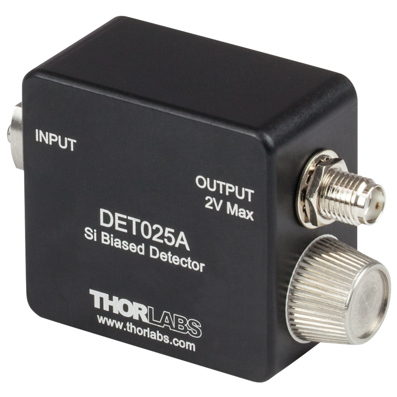
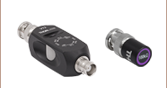
Click to Enlarge
SMA Output on the DET025A Detector
The DET025A(/M) and DET025AL(/M) high-speed, free-space detectors are designed for use in the 400 - 1100 nm spectral range. The DET025A(/M) has a flat, AR coated window at the input aperture, while the DET025AL(/M) uses the FDS025 photodiode which has an uncoated ball lens at the input aperture that focuses light onto the detector.
Both detectors have a 2 GHz bandwidth. An 8-32 tapped mounting hole (M4 for the metric version) allows easy mounting to our Ø1/2" posts.
| Item # | Wavelength | Detector | Input | Bandwidth | Max Peak Power | Bias Voltage |
Rise Time | Fall Time |
|---|---|---|---|---|---|---|---|---|
| DET025A(/M) | 400 - 1100 nm | Si | Flat AR-Coated Window |
2 GHz | 18 mW | 12 V | 150 ps (Typ.) |
150 ps (Typ.) |
| DET025AL(/M) | Uncoated N-BK7 Ball Lens |

 Zoom
Zoom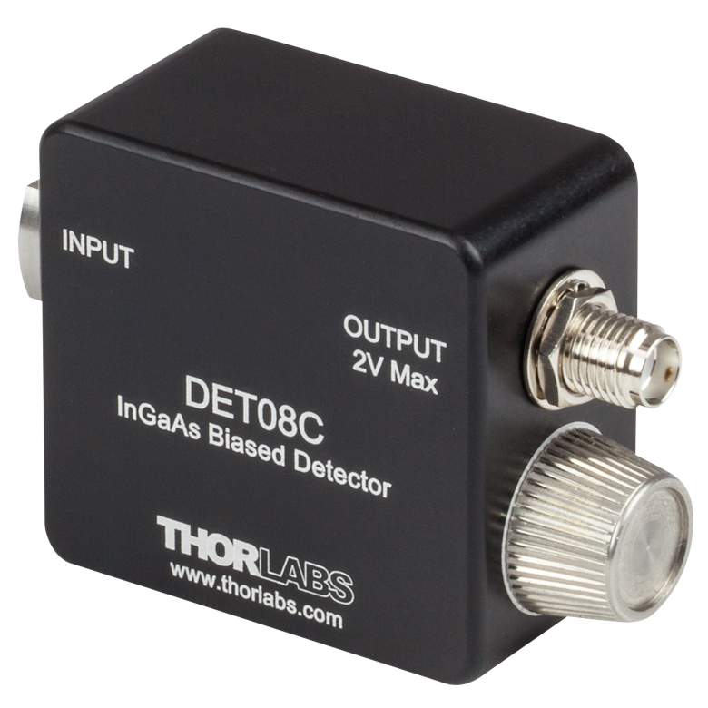
Click to Enlarge
SMA Output on the DET08C Detector
The DET08C(/M) and DET08CL(/M) high-speed, free-space detectors are designed for use in the 800 - 1700 nm spectral range. The DET08C(/M) detector has a flat, AR-coated window at the input aperture, while the DET08CL(/M) detector has an uncoated ball lens at the input aperture that focuses the light onto the detector.
These detectors use an InGaAs detector element and feature a 5 GHz bandwidth. An 8-32 tapped mounting hole (M4 for the metric version) allows easy mounting to our series of Ø1/2" posts.
| Item # | Wavelength | Detector | Input | Bandwidth | Max Peak Power | Bias Voltage |
Rise Time | Fall Time |
|---|---|---|---|---|---|---|---|---|
| DET08C(/M) | 800 - 1700 nm | InGaAs | Flat, AR-Coated Window |
5 GHz | 100 mW | 12 V | 70 ps (Typ.) |
110 ps (Typ.) |
| DET08CL(/M) | Uncoated N-BK7 Ball Lens |

 Zoom
Zoom
The A23 is a replacement alkaline battery for Thorlabs' DET photodetectors. For cases where the finite lifetime of a battery is not acceptable, we also offer an AC power adapter; please see below for more information. Information on expected battery lifetime is in the Battery Lifetime tab above.

 Zoom
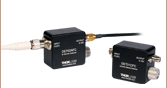
Zoom- DET2A: Power Adapter for DET Series Detectors
- LDS12B: ±12 VDC Power Supply
- DET2B: Bundle of the DET2A and LDS12B
DET2A Power Adapter
The DET2A is a power adapter for our DET series detectors. This power adapter will directly replace the A23 battery and spring-loaded cap to allow the detector to run directly from our LDS12B power supply (sold separately). The DET2A is also compatible with the PDA-C-72 power supply cable for custom connections. Note that when connecting the DET2A and the PDA-C-72 to power DET series detectors, only the brown (+12 V) and black (GND) pins are needed.
LDS12B Power Supply
The LDS12B is a ±12 VDC regulated power supply, which incorporates a current limit, enabling short circuit and overload protection; an on/off switch with an LED indicator; and a switchable AC input voltage (100, 120, or
230 VAC). A region-specific power cord is shipped with the LDS12B power supply based on your location.
DET2B Power Adapter Bundle
The DET2B power adapter bundle includes both the DET2A power adapter and the LDS12B power supply. This power adapter bundle can be used to replace the battery in our DET series detectors. To use the DET2B, simply replace the battery and spring-loaded cap with the included DET2A adapter, insert the 3-pin plug from the LDS12B power supply into the adapter, and screw the adapter into the detector. This procedure is depicted in the animation to the above right.