 Products Home / Drivers & Mounts / Dual Current / Temperature Controllers / Quantum Cascade Laser (QCL) Controllers, Current and TEC
Quantum Cascade Laser (QCL) Controllers, Current and TEC
- High Compliance Voltages Designed to Support QCL Lasers
- Drive Currents up to 2 A or 5 A
- Provides TEC Currents up to ±15 A
- 0.002 °C Temperature Stability Over 24 hrs
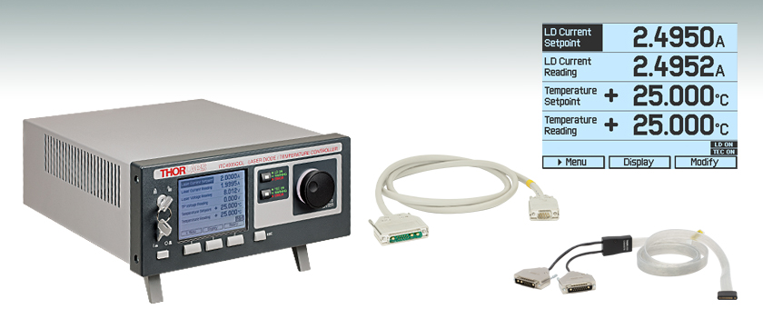
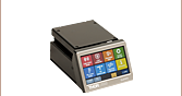
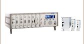
ITC4005QCL
Designed for Driving QCLs
CAB4007B
Laser Diode /TEC Cable
for HHL Packages
The main measurement display
shows readout values and device
status information.
CAB4005
Laser Diode Cable


Please Wait
Features
- High Compliance Voltage Supports High-Power QCLs
- 17 V for ITC4002QCL
- 20 V for ITC4005QCL
- Drive Lasers with Operating Currents ≤2 A (ITC4002QCL) or ≤5 A (ITC4005QCL)
- Continuous Wave (CW) or Quasi-Continuous Wave (QCW) Operation
- Also Capable of Driving LEDs
- Active Power Management for Efficient Operation
- Excellent Temperature Stability: 0.002 °C (24 hrs)
- Digital PID Control with Separate P, I, D Settings
- Auto PID Tuning Function
- Adjustable Temperature Sensor Offset
- Laser Diode (LD) and TEC Cables Available
- Dual LD / TEC Cables For HHL Lasers (Item #'s CAB4007A and CAB4007B)
- Standard LD Cable (Item # CAB4005)
- Standard and High Current TEC Cables (Item #'s CAB4000 and CAB4001)
| Item #a | ITC4002QCL | ITC4005QCL |
|---|---|---|
| Current Control Range | 0 to 2 A | 0 to 5 A |
| Compliance Voltage | 17 V | 20 V |
| Photocurrent Measurement Ranges | 2 mA / 20 mA | |
| QCWb Mode Pulse Width Range | 100 µs to 1 s | |
| QCWc Repetition Rate Range | 1 ms to 5 s (0.2 to 1000 Hz) | |
| TEC Current Range | -15 to +15 Ad | |
| TEC Compliance Voltage | >15 V | |
| TEC Output Power (Max) | >225 W | |
| Temperature Range (Max) | -150 to +150 °Cc | |
| Supported Temperature Sensors |
Thermistors (TH10K), Pt100 (TH100PT), Pt1000, AD590, AD592, LM335, LM235, LM135, LM35 | |
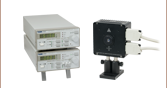
Thorlabs' Combined Laser Current and TEC Controllers are designed with a high compliance voltages of 17 V (ITC4002QCL) or 20 V (ITC4005QCL), enabling support for our entire selection of Quantum Cascade Lasers (QCLs). These devices combine the functionality of an LDC4000 series current controller and a TED4015 temperature controller into a single controller. The ITC4002QCL and ITC4005QCL supply precise, stable currents for lasers with a maximum operating current of 2 A or 5 A, respectively. Both devices provide excellent temperature stabilization to within 0.002 °C over a period of 24 hrs. For optimal noise performance, choose a controller that has maximum current and voltage ratings as close as possible to, but still higher than, the required voltage and current needed to operate your laser.
The controllers are compatible with all laser diode and monitor diode pin configurations, as well as our two-tab C-mount and HHL QCL and ICL packages. They feature a constant current (CC) or constant power (CP) mode. Most common temperature sensors can be used, and the contollers can be adapted to different thermal loads via a digital PID controller, which can operate through the built-in auto-tune PID function or separate control of the P, I, and D parameters. For more details about these features, please see the More Info tab.
The ITC4002QCL and ITC4005QCL controllers can be controlled via front panel keys and intuitive operation menus on a large and easy-to-read graphic LCD display (see the Display tab for sample screens). Alternatively, these controllers can be controlled by a SCPI-compatible USB Interface. Higher settings and measurement resolution are offered via USB operation, since the front panel resolution is limited by the resolution and refresh rate of the front panel display. Various outputs and a digital I/O port offer many control and connectivity options. The built-in function generator allows analog modulation of the laser output out of the box.
These controllers offer many advanced features such as Quasi-Continuous Wave (QCW) operation mode, easy auto-tune PID, and diverse laser and TEC element protection (see the More Info tab). The controller design also provides silent and power-efficient operation. These features make the ITC4002QCL and ITC4005QCL ideal choices for safe and secure operation of medium- to high-power QCLs, ICLs, and laser diodes either in the lab or in production environments. Thorlabs recommends recalibrating these controllers every 24 months and offers a factory recalibration service. To order this service, scroll to the bottom of the page and select Item # CAL-ITC4.
Thorlabs offers Laser Current and TEC connector cables to ensure safe and reliable connections between these controllers and the laser. The CAB4007A and CAB4007B dual LD / TEC connector cables are designed for use with HHL laser packages. The CAB4007A cable is designed specifically to connect the controllers to Thorlabs' LCM100(/M) Liquid-Cooled Mount for HHL Lasers. The CAB4007B cable is designed to be used to connect any standard 10-pin HHL laser package to our ITC400xQCL controllers. The CAB4005 LD Cable and CAB4000 TEC Cable are the standard, 5A connector cables that are shipped with each ITC4002QCL and ITC4005QCL. The CAB4001 TEC cable is a high-current cable rated for up to 20 A.
We also offer combined laser current and TEC controllers which have a lower compliance voltage of 11 V or 12 V.
For driver software, as well as programming reference guides for the Programmable Instruments (SCPI) standard, LabVIEW™, Visual C++, Visual C#, and Visual Basic, please see the Software tab.
Laser Operation Modes
The lasers can be driven in either Constant Current (CC) mode, where the laser current is held precisely at the level adjusted by the user, or Constant Power (CP) mode, where an optical power sensor is used to monitor the output power of the laser for active power control. The CC mode is preferable when the lowest noise and highest response speed are required, but this mode generally requires temperature stabilizing as well. In CP mode, feedback from the internal photodiode integrated into most laser packages, an external photodiode, or other sensor is used to actively stabilize the laser's output power.
100 µs Pulses of 20 A
Figure: Oscilloscope screenshot of a typical short 100 µs Pulse of 20.0 A generated by the ITC4020 in QCW mode
The ITC4002QCL and ITC4005QCL each offer two independent monitor inputs: one for photodiodes and one for thermopiles, either of which can be chosen for controlling the laser. The analog modulation via external input or the internal function generator allows modulation of the laser in CC and CP modes. A control output voltage proportional to the laser current is provided for monitoring purposes.
Pulsed Operation
Depending on the application, the ITC4000 Series of laser drivers can be operated in Continuous Wave (CW) or Quasi-CW (QCW) mode. To demonstrate the performance of these controllers, a screenshot of an oscilloscope measuring the output current of an ITC4020 in QCW mode is shown to the right. The ITC4020 produces sharp and accurate 100 µs pulses with a peak current of 20 A without any unwanted overshoots. The ITC4002QCL and ITC4005QCL will provide similar performance within their respective current ranges. The integrated pulse generator can be triggered internally with an adjustable repetition rate or externally via a BNC jack at the rear of the unit.
Enhanced Protection Features for the Laser
Current Limit: A precisely adjustable current limit ensures that the maximum laser current cannot be exceeded. Thorlabs has intentionally provided limited access to this feature to prevent accidental adjustment. An attempt to increase the laser drive current above the preset limit will result in a visible and short audible indicator. Even when utilizing the external modulation feature, the current limit setpoint cannot be exceeded.
Current Source: If the connection between the current source and laser is interrupted, the current source automatically switches off the current output. The open current circuit condition is indicated by the “OPEN” indicator on the controller and a short acoustic warning. The separate laser ON key switches the laser current on and off. When switched off, an electronic switch within the device short circuits the laser for added protection. After being switched on, a soft start ensures a slow increase of the laser current without voltage peaks. Even in the case of line failure, the laser current remains transient free. Voltage peaks on the AC line are effectively suppressed by electrical filters, shielding of the transformer, and careful grounding of the chassis.
TEC Controller
The ITC4002QCL and ITC4005QCL contain high-performance digital TEC controllers for currents up to ±15 A. They offer excellent temperature stability of 0.002 °C within 24 hrs together with the same enhanced safeguard and operation features of Thorlabs' TED4015. The digital PID controller can adapt to different thermal loads by individually adjustable parameters or by the auto PID function (for more details see the full presentation for the TED4015). The maximum control range of the temperature sensor input spans 100 Ω to 1 MΩ for thermistors and -55 to 150 °C for temperature sensing ICs or Platinum RTD sensors. The actual applicable temperature range is limited by the connected sensor and the thermal setup. For maximum TEC element protection, the ITC offers the same features as the TED4015. These protection features include an adjustable TEC output current limit and temperature sensor malfunction alerts.
These controllers provides a monitoring signal proportional to the difference between actual and set temperature. An oscilloscope or an analog data acquisition card can be connected to the rear panel BNC connector to monitor the settling behavior with different thermal loads.
Laser Current Controller
| Item # | ITC4002QCL | ITC4005QCL | ||
|---|---|---|---|---|
| Front Panela | Remote Controla | Front Panela | Remote Controla | |
| Current Control (Constant Current Mode) | ||||
| Laser Diode Current Range | 0 to 2 A | 0 to 5 A | ||
| Compliance Voltage | 17 V | 20 V | ||
| Setting / Measurement Resolution | 100 µA | 32 µA | 1 mA | 80 µA |
| Accuracy | ±(0.1% + 800 µA) | ±(0.1% + 2 mA) | ||
| Noise and Ripple (10 Hz to 10 MHz, RMS, Typical, w/o Noise Reduction Filter) |
<20 µA | <250 µA | ||
| Noise and Ripple (10 Hz to 10 MHz, RMS, Typical, w/ Noise Reduction Filter) |
<5 µA | <50 µA | ||
| Drift, 24 Hours (0-10 Hz, Typical, at Constant Ambient Temperature) |
<150 µA | <300 µA | ||
| Temperature Coefficient | ≤50 ppm/°C | |||
| Current Limit | ||||
| Setting Range | 2 mA to 2 A | 5 mA to 5 A | ||
| Setting Resolution | 100 µA | 32 µA | 1 mA | 80 µA |
| Accuracy | ±(0.12% + 1.6 mA) | ±(0.12% + 3 mA) | ||
| Power Monitor Input - Photodiode | ||||
| Photocurrent Measurement Ranges | 0 to 2 mA / 0 to 20 mA | |||
| Photocurrent Measurement Resolution (2 mA Range / 20 mA Range) |
1 µA / 10 µA | 32 nA / 320 nA | 1 µA / 10 µA | 32 nA / 320 nA |
| Photocurrent Accuracy (2 mA Range / 20 mA Range) |
±(0.08% + 0.5 µA) / ±(0.08% + 5 µA) | |||
| Photodiode Reverse Bias Voltage | 0 to 10 V | |||
| Photodiode Input Impedance | ~0 Ω (Virtual Ground) | |||
| Power Monitor Input - Thermopileb | ||||
| Voltage Measurement Ranges | 0 to 10 mV / 0 to 100 mV / 0 to 1 V / 0 to10 V | |||
| Voltage Measurement Resolution (for 10 mV / 100 mV / 1 V / 10 V Ranges) |
1 µV / 10 µV / 100 µV / 1 mV |
0.16 µV / 1.6 µV / 16 µV / 160 µV |
1 µV / 10 µV / 100 µV / 1 mV |
0.16 µV / 1.6 µV / 16 µV / 160 µV |
| Voltage Measurement Accuracy (for 10 mV / 100 mV / 1V / 10 V Ranges) |
±(0.1% + 10 µV) / ±(0.1% + 100 µV) / ±(0.1% + 1 mV) / ±(0.1% + 5 mV) |
|||
| Voltage Input Impedance | 1 MΩ | |||
| Laser Power Control (Constant Power Mode) | ||||
| Photocurrent Control Rangesc | 0 to 2 mA / 0 to 20 mA | |||
| Photocurrent Setting Resolution | 1 µA / 10 µA | 32 nA / 320 nA | 1 µA / 10 µA | 32 nA / 320 nA |
| Thermopile Voltage Control Rangesc | 1 µV to 10 mV / 10 µV to 100 mV / 100 µV to 1 V / 1 mV to 10 V |
|||
| Thermopile Voltage Setting Resolution | 1 µV / 10 µV / 100 µV / 1 mV |
0.16 µV / 1.6 µV / 16 µV / 160 µV |
1 µV / 10 µV 100 µV / 1 mV |
0.16 µV / 1.6 µV / 16 µV / 160 µV |
| Power Limit (Constant Power Mode) | ||||
| Photocurrent Limit Setting Rangesc | 5 µA to 2 mA / 50 µA to 20 mA | |||
| Photocurrent Limit Resolution (2 mA Range/ 20 mA Range) | 1 µA / 10 µA | 128 nA / 1.28 µA | 1 µA / 10 µA | 128 nA / 1.28 µA |
| Photocurrent Limit Accuracy | ±20 µA / ±200 µA | |||
| Thermopile Voltage Limit Setting Rangesc | 1 µV to 10 mV / 10 µV to 100 mV / 100 µV to 1V / 1 mV to 10V | |||
| Thermopile Voltage Limit Resolution | 1 µV / 10 µV / 100 µV / 1 mV |
730 nV / 7.3 µV / 73 µV / 730 µV |
1 µV / 10 µV 100 µV / 1 mV |
730 nV / 7.3 µV 73 µV / 730 µV |
| Thermopile Voltage Limit Accuracy | ±10 µV / ±100 µV / ±1 mV / ±10 mV | |||
| Front Panela | Remote Controla | Front Panela | Remote Controla | |
| Laser Voltage Measurement | ||||
| Measurement Principle | 4-Wire | |||
| Measurement Resolution | 1 mV | 320 µV | 1 mV | 320 µV |
| Accuracy | ±30 mV | |||
| Laser Overvoltage Protection | ||||
| Setting Range | 1 V to 17 V | 1 V to 20 V | ||
| Resolution | 1 mV | |||
| Accuracy | ±70 mV | |||
| Laser Current Monitor Output | ||||
| Load Resistance | >10 kΩ | |||
| Transmission Coefficient | 5 V/A ± 5% | 2 V/A ± 5% | ||
| External Modulation Input | ||||
| Input Impedance | 10 kΩ | |||
| Small Signal 3dB Bandwidth, CC Mode w/o Noise Reduction Filter |
DC to 130 kHz (2 Ω Load) | DC to 100 kHz (1 Ω Load) DC to 50 kHz (5 Ω Load) |
||
| Small Signal 3dB Bandwidth, CC Mode w/ Noise Reduction Filter |
DC to 10 kHz (2 Ω Load) | DC to 6 kHz (1 Ω Load) DC to 5 kHz (5 Ω Load) |
||
| Modulation Coefficient, CC Mode | 200 mA/V ± 5% | 500 mA/V ± 5% | ||
| Modulation Coefficient, CP Mode, Current Sensorc | 200 µA/V / 2 mA/V ± 5% | |||
| Modulation Coefficient, CP Mode, Voltage Sensorc | 1 mV/V / 10 mV/V / 100 mV/V / 1 V/V ± 5% | |||
| Internal Laser Modulation | ||||
| Waveforms | Sine, Square, Triangle | |||
| Frequency Range | 20 Hz to 130 kHz | 20 Hz to 100 kHz | ||
| Modulation Depth | 0.1 to 100% | |||
| QCW Mode | ||||
| Pulse Width Range | 100 µs to 1 s | |||
| Pulse Width Resolution | 1 µs | |||
| Repetition Rate Range | 1 ms to 5 s (0.2 to 1000 Hz) | |||
| Repetition Rate Resolution | 10 µs | |||
| Trigger | ||||
| Input | Rising Edge Triggered, Starts QCW Pulse with Internal Adjusted Width | |||
| Input Level | TTL or 5 V CMOS | |||
| Output | Active High, Tracks Pulse Width | |||
| Output Level | TTL or 5 V CMOS | |||
| Death Time to Next Pulse | >10 µs | |||
Temperature Control
| Item # | ITC4002QCL | ITC4005QCL | ||
|---|---|---|---|---|
| Front Panela | Remote Controla | Front Panela | Remote Controla | |
| TEC Current Control | ||||
| Control Range | -15 to +15 A | |||
| Compliance Voltage | >15 V | |||
| Maximum Output Power | >225 W | |||
| Resolution, CC Mode | 1 mA | 0.1 mA | 1 mA | 0.1 mA |
| Accuracy | ± (0.2% + 20 mA) | |||
| Noise and Ripple (Typical) | <10 mA rms | |||
| TEC Current Limit | ||||
| Setting Range | 0.1 A to 15 Ab | |||
| Resolution | 1 mA | 0.1 mA | 1 mA | 0.1 mA |
| Accuracy | ± (0.2% + 10 mA) | |||
| NTC Thermistor Sensors | ||||
| Resistance Measurement Ranges | 100 Ω to 100 kΩ / 1 kΩ to 1 MΩ | |||
| Control Range Maxc | -150 to +150 °C | |||
| Temperature Resolution | 0.001 °C | |||
| Resolution (Resistance, 100 kΩ/1 MΩ Range) | 0.1 Ω / 1 Ω | 0.03 Ω / 0.3 Ω | 0.1 Ω / 1 Ω | 0.03 Ω / 0.3 Ω |
| Accuracy (100 kΩ/1 MΩ Range) | ± (0.06% + 1 Ω / 5 Ω) | |||
| Temperature Stability (24 hours Typ.)c | <0.002 °C | |||
| Temperture Coefficient | <5 mK/°C | |||
| IC Sensors | ||||
| Supported Current Temperature Sensors | AD590, AD592 | |||
| Supported Voltage Temperature Sensors | LM335, LM235, LM135, LM35 | |||
| Control Range with AD590 | -55 to +150 °C | |||
| Control Range with AD592 | -25 to +105 °C | |||
| Control Range with LM335 | -40 to +100 °C | |||
| Control Range with LM235 | -40 to +125 °C | |||
| Control Range with LM135 | -55 to +150 °C | |||
| Control Range with LM35 | -55 to +150 °C | |||
| Resolution | 0.001 °C | 0.0001 °C | 0.001 °C | 0.0001 °C |
| Accuracy AD590 Current | ± (0.04% + 0.08 µA) | |||
| Accuracy LM335/LM35 Voltage | ± (0.03% + 1.5 mV) | |||
| Temperature Stability (24 hours) | <0.002 °C | |||
| Temperature Coefficient | <5 mK/°C | |||
| Front Panela | Remote Controla | Front Panela | Remote Controla | |
| Pt100/Pt1000 RTD Sensors | ||||
| Temperature Control Range | -55 to +150 °C | |||
| Resolution | 0.001 °C | 0.0003 °C | 0.001 °C | 0.0003 °C |
| Accuracy (4-Wire Measurement) | ±0.3 °C | |||
| Temperature Stability (24 hours) | <0.005 °C | |||
| Temperature Coefficient | <20 mK/°C | |||
| Temperature Window Protection | ||||
| Setting Range Twin | 0.01 to 100.0 °C | |||
| Protection Reset Delay | 0 to 600 s | |||
| Window Protection Output | TTL or 5 V CMOS | |||
| Temperature Control Output | ||||
| Load Resistance | >10 k Ω | |||
| Transmission Coefficient | ΔT * 5V / Twin ±0.2 % (Temperature Deviation, Scaled to Temperature Window) | |||
| TEC Voltage Measurement | ||||
| Measurement Principle | 4-Wire/2-Wire | |||
| Resolution | 100 mV | 40 mV | 100 mV | 40 mV |
| Accuracy (with 4-Wire Measurement) | ±50 mV | |||
General Specifications
| Item # | ITC4002QCL | ITC4005QCL |
|---|---|---|
| Digital I/O Port | ||
| Number of I/O Lines | 4 (Separately Configurable) | |
| Input Level | TTL or CMOS, Voltage Tolerant up to 24 V | |
| Output Level (Source Operation) | TTL or 5 V CMOS, 2 mA Max | |
| Output Level (Sink Operation) | Open Collector, up to 24 V, 400 mA Max | |
| Interface | ||
| USB 2.0 | According to USBTMC/USBTMC-USB488 Specification Rev. 1.0 | |
| Protocol | SCPI Compliant Command Set | |
| Drivers | VISA VXIpnp™, MS Visual Studio™, MS Visual Studio.net™, NI LabVIEW™, NI LabWindows/CVI™ |
|
| General Data | ||
| Safety Features | Interlock, Inhibit, Keylock Switch, Laser Current Limit, Laser Power Limit, Soft Start, Short Circuit when Laser off, Adjustable Laser Overvoltage Protection, Over Temperature Protection Temperature Window Protection |
|
| Display | LCD 320 x 240 Pixel | |
| Connector for Laser, Photodiode, Interlock, and Laser On Signal |
13W3 Mixed D-Sub Jack (Female) | |
| Connector for Sensor, TE Cooler, TEC On Signal | 17W2 Mixed D-Sub Jack (Female) | |
| Connectors for Control Input / Output | BNC | |
| Connector for Digital I/O | Mini DIN 6 | |
| Connector for USB-Interface | USB Type B | |
| Chassis Ground Connector | 4 mm Banana Jack | |
| Line Voltage / Frequency | 100 to 120 V and 200 to 240 V ±10%, 50 to 60 Hz | |
| Maximum Power Consumption | 600 VA | 880 VA |
| Mains Supply Overvoltage | Category II (Cat II) | |
| Operating Temperature | 0 to 40 °C | |
| Storage Temperature | - 40 to +70 °C | |
| Relative Humidity | Max 80% Up to 31 °C, Decreasing to 50% at 40 °C | |
| Pollution Degree (Indoor Use Only) | 2 | |
| Operation Altitude | <2000 m | |
| Warm-up Time for Rated Accuracy | 30 min | |
| Weight | 6.4 kg | |
| Dimensions without Operating Elements (W x H x D) |
263 mm x 122 mm x 307 mm (10.4" x 4.8" x 12.1") |
|
| Dimensions with Operating Elements (W x H x D) |
263 mm x 122 mm x 345 mm (10.4" x 4.8" x 13.6") |
|
All technical data valid at 23 ± 5 °C and 45 ± 15% relative humidity. Subject to change without notice.
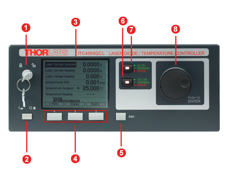
ITC4000 Controllers Front Panel
| Callout | Connection | Callout | Connection |
|---|---|---|---|
| 1 | Key Switch | 5 | Escape Key |
| 2 | Supply Power Switch | 6 | TEC Status Indicator |
| 3 | LC Display | 7 | LD Status Indicator |
| 4 | Softkeys for Menu Navigation | 8 | Adjustment Knob |
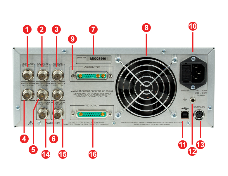
ITC4000 Controllers Back Panel
| Callout | Connection | Callout | Connection |
|---|---|---|---|
| 1 | TTL Input "Laser Enable In" 5 V Max | 9 | LD Output and Optical Sensor Input "Laser Output" |
| 2 | TTL Input "QCW Pulse In" 5 V Max | 10 | Power Connector and Fuse Holder "Line In" |
| 3 | TTL Output "Trigger Out" 0 - 5 V | 11 | USB Connector |
| 4 | Optical Sensor Input "Opt Sensor In" 0 to 10 V Max |
12 | 4 mm Banana Jack for Chassis Ground |
| 5 | Modulation input "Modulation In" -10 to 10 V |
13 | MiniDin-6 Jack "Digital I/O" |
| 6 | Laser Current Monitor "Analog CTL Out" 0 - 10 V |
14 | Actual Temperature Deviation Output "Deviation Out" -5 to 5 V |
| 7 | Serial Number of the Unit | 15 | TTL Temperature Monitor Output "Temp OK Out" 5 V |
| 8 | Cooling Fan | 16 | TEC Element Output and Temperature Sensor Input "TEC Output" |
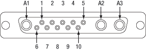
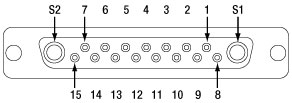
LD Output
13W3 Mixed D-Sub Jack
| Pin | Connection | Pin | Connection |
|---|---|---|---|
| 1 | (Thermo) Voltage Sensor Input (+) | 7 | Photo Current Sensor Input (+) |
| 2 | (Thermo) Voltage Sensor Ground (-) | 8 | Photo Current Sensor Ground (-) |
| 3 | Not Connected | 9 | Not Connected |
| 4 | Laser Diode Anode (+) | 10 | Laser Diode Cathode (-) |
| 5 | Output for Interlock and Status Indicator "LASER ON/OFF" (+) | A1 | Laser Diode Ground |
| 6 | Ground Pin for Interlock and Status Indicator "LASER ON/OFF" (-) | A2 | Laser Diode Cathode (with Polarity AG) (-) |
| A3 | Laser Diode Anode (with Polarity CG) (+) |
TEC Output
17W2 Mixed D-Sub Jack
| Pin | Connection | Pin | Connection |
|---|---|---|---|
| 1 | Interlock, TEC ON LED (+) | 10 | PT100/1000 (-), AD590/592 (-), LM35 Out, LM135/235/335 (+) |
| 2 | Voltage Measurement TEC Element (+) | 11 | PT100/1000 (+), AD590/592 (+), LM35/135/235/335 (+) |
| 3 | Thermistor (-), PT100/1000 (-), Analog Ground | 12 | Analog Ground, LM35/135/235/335 (-) |
| 4 | Thermistor (+), PT100/1000 (+) | 13 | Not Connected |
| 5 | Analog Ground, LM35/135/235/335 (-) | 14 | I/O 1-wire (Currently Not Used) |
| 6 | Digital Ground for I/O 1-wire | 15 | Ground for 12 V Output and Interlock, TEC ON LED (-) |
| 7 | 12 V Output (for External Fan, max. current = 500 mA) | S1 | TEC Element (+) (Peltier Element) |
| 8 | Not Connected | S2 | TEC Element (-) (Peltier Element) |
| 9 | Voltage Measurement TEC Element (-) |
Digital I/O Ports
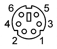
| Pin | Connection |
|---|---|
| 1 | I/O 1 |
| 2 | I/O 2 |
| 3 | I/O 3 |
| 4 | I/O 4 |
| 5 | GND |
| 6 | I/O Supply Voltage (+12 V from internal or higher external voltage up to +24 V) |
LD Enable In
BNC Female
Laser Enable Input (High to Enable Laser ON), TTL 5 V Max
QCW Pulse In
BNC Female
Input for External Trigger Signal, TTL 5 V Max
Trigger Out
BNC Female
QCW Pulse Tracking Output, TTL 5 V
OPT Sensor In
BNC Female
Input for Optical Sensor, 0 to +10 V Max
Modulation In
BNC Female
Input for External Modulation Signal, -10 to +10 V Max
Analog CTL Out
BNC Female
Output for Laser Current Monitoring, 0 to +10 V
Deviation Out
BNC Female
Actual Temperature Deviation Output, -5 to +5 V
Temp OK Out
BNC Female
Temperature OK Output (High if Inside Temperature Window), TTL 5 V
Computer Connection
USB Type B
USB Type B to Type A Cable Included
Ground
4 mm Banana Jack for Chassis Ground
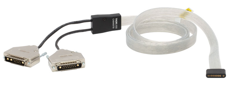
CAB4007A Laser Diode / TEC Cable
This cable is made of a highly flexible flat cable and contains a 9W4 male connector on one end and 17W2 and 13W3 male connectors on the other end. The CAB4007A is designed for connecting an LCM100(/M) liquid-cooled mount to a Thorlabs ITC400xQCL series controller.

17W2 Male Connector

13W3 Male Connector
9W4 Male Connector
| CAB4007A | ||||
|---|---|---|---|---|
| 9W4 Pin | Signal | 13W3 Pin | 17W2 Pin | Max Current Input |
| A4 | TEC Cathode (-) | No Connection | A2 | 11 A |
| 2 | No Connection | No Connection | No Connection | 5 A |
| A3 | Laser Anode (+) | A3 | No Connection | 11 A |
| 1 | Thermistor (+) | No Connection | 4 | 5 A |
| 3 | Thermistor (-) | No Connection | 3 | 5 A |
| A2 | Laser Cathode (-) | A2 | No Connection | 11 A |
| 4 | EEPROM (+) | 3 | No Connection | 5 A |
| 5 | EEPROM (- / Ground) | 9 | No Connection | 5 A |
| A1 | TEC Anode (+) | No Connection | A1 | 11 A |
| No Connection | Laser Driver Interlock | 5, 6 | No Connection | - |
| No Connection | TEC Driver Interlock | No Connection | 1, 15 | - |
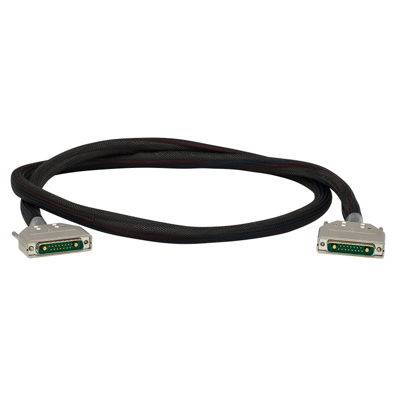
CAB4007B Laser Diode / TEC Cable
This cable is made of a highly flexible flat cable and contains a Flat 10-Pin HHL Female connector on one end and 17W2 and 13W3 male connectors on the other end. The CAB4007B is designed for connecting any laser with a standard 10-Pin HHL package to a Thorlabs ITC400xQCL series controller.
17W2 Male Connector
13W3 Male Connector
Flat 10-Pin HHL Female Connector
| CAB4007B | ||||
|---|---|---|---|---|
| Flat 10-Pin Connector | Signal | 13W3 Pin | 17W2 Pin | Max Current Input |
| 1 | TEC Cathode (-) | No Connection | A2 | 10 A |
| 3 | No Connection | No Connection | No Connection | 5 A |
| 4 | Laser Anode (+) | A3 | No Connection | 10 A |
| 5 | Thermistor (+) | No Connection | 4 | 5 A |
| 6 | Thermistor (-) | No Connection | 3 | 5 A |
| 7 | Laser Cathode (-) | A2 | No Connection | 10 A |
| 8 | EEPROM (+) | 3 | No Connection | 5 A |
| 9 | EEPROM (- / Ground) | 9 | No Connection | 5 A |
| 10 | TEC Anode (+) | No Connection | A1 | 10 A |
| No Connection | Laser Driver Interlock | 5, 6 | No Connection | - |
| No connection | TEC Driver Interlock | No Connection | 1, 15 | - |
CAB4005 Laser Diode Cable
This cable contains a DB-9 male connector on one side and a 13W3 male connector on the other side. Both views shown below are looking into the connector.
DB-9 Male Connector
13W3 Male Connector
| Pin Matching | |
|---|---|
| DB-9 Pin | 13W3 Pin |
| 1 | 5 |
| 2 | 8 |
| 3 | A1 |
| 4 | 7 |
| 5 | 6 |
| 6 | 10 |
| 7 | A2 |
| 8 | A3 |
| 9 | 4 |
| Shield | Shield |
| DB-9 Connector Colors | |
|---|---|
| Pin | Color |
| 1 | White |
| 2 | Gray and Pink |
| 3 | Gray / Black (2 Wires) |
| 4 | Red and Blue |
| 5 | Brown |
| 6 | Blue |
| 7 | Yellow / Purple (2 Wires) |
| 8 | Green / Pink (2 Wires) |
| 9 | Red |
| 13W3 Connector Colors | |||
|---|---|---|---|
| Pin | Color | Pin | Color |
| 1 | No Connection | 9 | No Connection |
| 2 | No Connection | 10 | Blue |
| 3 | No Connection | A1 | Gray / Black (2 Wires) |
| 4 | Red | ||
| 5 | White | A2 | Yellow / Purple (2 Wires) |
| 6 | Brown | ||
| 7 | Red and Blue | A3 | Green / Pink (2 Wires) |
| 8 | Gray and Pink | ||
CAB4000 TEC Element Cable
This cable contains a DB-9 female connector on one side and a 17W2 male connector on the other side. Both views shown below are looking into the connector.
DB-9 Female Connector
 17W2 Male Connector
| Pin Matching | |
|---|---|
| DB-9 Pin | 17W2 Pin(s) |
| 1 | 1, 15 |
| 2 | 4 |
| 3 | 3 |
| 4 | 2, S1 |
| 5 | 9, S2 |
| 6 | No Connection |
| 7 | 10 |
| 8 | 5, 12 |
| 9 | 11 |
| Shield | Shield |
| DB-9 Connector Colors | |
|---|---|
| Pin | Color |
| 1 | White |
| 2 | Pink and Gray |
| 3 | Red and Blue |
| 4 | Pink / Red / Purple (3 Wires) |
| 5 | Black / Gray / Blue (3 Wires) |
| 6 | No Connection |
| 7 | Yellow |
| 8 | Brown |
| 9 | Green |
| 17W2 Connector Colors | |||
|---|---|---|---|
| Pin | Color | Pin | Color |
| 1 | White | 11 | Green |
| 2 | Red | 12 | Brown |
| 3 | Red and Blue | 13 | No Connection |
| 4 | Pink and Gray | 14 | No Connection |
| 5 | Brown | 15 | White |
| 6 | No Connection | S1 | Purple / Pink (2 Wires) |
| 7 | No Connection | ||
| 8 | No Connection | S2 | Black / Gray (2 Wires) |
| 9 | Blue | ||
| 10 | Yellow | ||
Sample Screens
| Measurement Screen 1 | Measurement Screen 2 | ||
|---|---|---|---|
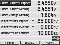 |
The measurement screen offers easy readout of measurement values and device status information. It also allows the major instrument setpoints to be adjusted. You can freely select two, four, or six values to be displayed with optimized character size. | 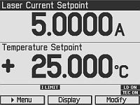 |
Here the measurement screen is configured to 2 values. The character size is enlarged as much as possible for easier reading. |
| Menu Screen | QCW Settings Screen | ||
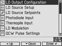 |
The menu screen allows various operation modes and options to be selected. | 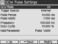 |
This is the input screen for the Quasi-Continuous Wave (QCW) pulse mode settings, e.g. trigger source and pulse parameters. |
| Laser Diode Setup Screen | Photodiode Input Screen | ||
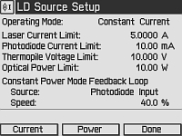 |
The laser diode setup screen allows the user to enter essential laser control parameters: constant current or constant power mode, limits for laser current and laser power, speed and source of the constant power feedback loop. |
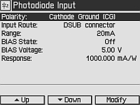 |
All parameters concerning the photodiode sensor are entered via the Photodiode Input Screen. |
| Temperature Controller Screen | Temperature Mode Settings Screen | ||
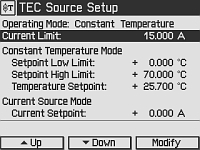 |
All parameters for the temperature controller are entered via the Temperature Controller Screen: Operation Mode, Current Limit, Current Control Mode Settings, Temperature Sensor Settings. | 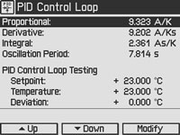 |
For manual optimization, the temperature PID control loop settings can be entered here. Temperature setpoint and actual reading are accessible for convenient testing. |
| PID Auto-Tune Screen | Preferences Screen | ||
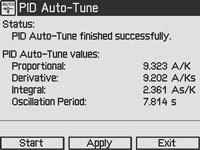 |
The PID auto-tune function is started via this screen. The controller automatically selects the optimal PID parameters for the current thermal setup. | 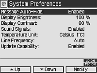 |
The preferences screen offers access to the device preferences, e.g. display and signal settings. |
Software for Laser Diode Controllers
The download button below links to VISA VXI pnp™, MS Visual Studio™, MS Visual Studio.net™, LabVIEW™, and LabWindows/CVI™ drivers, firmware, utilities, and support documentation for Thorlabs' ITC4000 Series laser controllers, LDC4000 Series laser controllers, CLD1000 Series compact laser diode controllers, and TED4000 Series TEC controllers.
The software download page also offers programming reference notes for interfacing with compatible controllers using SCPI, LabVIEW, Visual C++, Visual C#, and Visual Basic. Please see the Programming Reference tab on the software download page for more information and download links.
Driver Software
Version 3.1.0 (April 11, 2014)
Programming Reference
Version 3.3 (April 8, 2015) - SCPI Commands
Version 1.0 (June 16, 2015) - LabVIEW, Visual C++, Visual C#, Visual Basic
The software packages support LabVIEW 8.5 and higher. If you are using an earlier version of LabVIEW, please contact Tech Support for assistance.
PID Basics
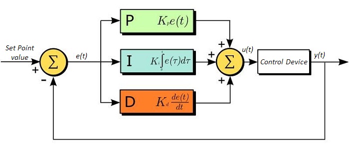
The PID circuit is often utilized as a control loop feedback controller and is very commonly used for many forms of servo circuits. The letters making up the acronym PID correspond to Proportional (P), Integral (I), and Derivative (D), which represents the three control settings of a PID circuit. The purpose of any servo circuit is to hold the system at a predetermined value (set point) for long periods of time. The PID circuit actively controls the system so as to hold it at the set point by generating an error signal that is essentially the difference between the set point and the current value. The three controls relate to the time-dependent error signal; at its simplest, this can be thought of as follows: Proportional is dependent upon the present error, Integral is dependent upon the accumulation of past error, and Derivative is the prediction of future error. The results of each of the controls are then fed into a weighted sum, which then adjusts the output of the circuit, u(t). This output is fed into a control device, its value is fed back into the circuit, and the process is allowed to actively stabilize the circuit’s output to reach and hold at the set point value. The block diagram below illustrates very simply the action of a PID circuit. One or more of the controls can be utilized in any servo circuit depending on system demand and requirement (i.e., P, I, PI, PD, or PID).
Through proper setting of the controls in a PID circuit, relatively quick response with minimal overshoot (passing the set point value) and ringing (oscillation about the set point value) can be achieved. Let’s take as an example a temperature servo, such as that for temperature stabilization of a laser diode. The PID circuit will ultimately servo the current to a Thermo Electric Cooler (TEC) (often times through control of the gate voltage on an FET). Under this example, the current is referred to as the Manipulated Variable (MV). A thermistor is used to monitor the temperature of the laser diode, and the voltage over the thermistor is used as the Process Variable (PV). The Set Point (SP) voltage is set to correspond to the desired temperature. The error signal, e(t), is then just the difference between the SP and PV. A PID controller will generate the error signal and then change the MV to reach the desired result. If, for instance, e(t) states that the laser diode is too hot, the circuit will allow more current to flow through the TEC (proportional control). Since proportional control is proportional to e(t), it may not cool the laser diode quickly enough. In that event, the circuit will further increase the amount of current through the TEC (integral control) by looking at the previous errors and adjusting the output in order to reach the desired value. As the SP is reached [e(t) approaches zero], the circuit will decrease the current through the TEC in anticipation of reaching the SP (derivative control).
Please note that a PID circuit will not guarantee optimal control. Improper setting of the PID controls can cause the circuit to oscillate significantly and lead to instability in control. It is up to the user to properly adjust the PID gains to ensure proper performance.
PID Theory
The output of the PID control circuit, u(t), is given as
where
Kp= Proportional Gain
Ki = Integral Gain
Kd = Derivative Gain
e(t) = SP - PV(t)
From here we can define the control units through their mathematical definition and discuss each in a little more detail. Proportional control is proportional to the error signal; as such, it is a direct response to the error signal generated by the circuit:
Larger proportional gain results is larger changes in response to the error, and thus affects the speed at which the controller can respond to changes in the system. While a high proportional gain can cause a circuit to respond swiftly, too high a value can cause oscillations about the SP value. Too low a value and the circuit cannot efficiently respond to changes in the system.
Integral control goes a step further than proportional gain, as it is proportional to not just the magnitude of the error signal but also the duration of the error.
Integral control is highly effective at increasing the response time of a circuit along with eliminating the steady-state error associated with purely proportional control. In essence integral control sums over the previous error, which was not corrected, and then multiplies that error by Ki to produce the integral response. Thus, for even small sustained error, a large aggregated integral response can be realized. However, due to the fast response of integral control, high gain values can cause significant overshoot of the SP value and lead to oscillation and instability. Too low and the circuit will be significantly slower in responding to changes in the system.
Derivative control attempts to reduce the overshoot and ringing potential from proportional and integral control. It determines how quickly the circuit is changing over time (by looking at the derivative of the error signal) and multiplies it by Kd to produce the derivative response.

Unlike proportional and integral control, derivative control will slow the response of the circuit. In doing so, it is able to partially compensate for the overshoot as well as damp out any oscillations caused by integral and proportional control. High gain values cause the circuit to respond very slowly and can leave one susceptible to noise and high frequency oscillation (as the circuit becomes too slow to respond quickly). Too low and the circuit is prone to overshooting the SP value. However, in some cases overshooting the SP value by any significant amount must be avoided and thus a higher derivative gain (along with lower proportional gain) can be used. The chart below explains the effects of increasing the gain of any one of the parameters independently.
| Parameter Increased | Rise Time | Overshoot | Settling Time | Steady-State Error | Stability |
|---|---|---|---|---|---|
| Kp | Decrease | Increase | Small Change | Decrease | Degrade |
| Ki | Decrease | Increase | Increase | Decrease Significantly | Degrade |
| Kd | Minor Decrease | Minor Decrease | Minor Decrease | No Effect | Improve (for small Kd) |
Tuning
In general the gains of P, I, and D will need to be adjusted by the user in order to best servo the system. While there is not a static set of rules for what the values should be for any specific system, following the general procedures should help in tuning a circuit to match one’s system and environment. In general a PID circuit will typically overshoot the SP value slightly and then quickly damp out to reach the SP value.
Manual tuning of the gain settings is the simplest method for setting the PID controls. However, this procedure is done actively (the PID controller turned on and properly attached to the system) and requires some amount of experience to fully integrate. To tune your PID controller manually, first the integral and derivative gains are set to zero. Increase the proportional gain until you observe oscillation in the output. Your proportional gain should then be set to roughly half this value. After the proportional gain is set, increase the integral gain until any offset is corrected for on a time scale appropriate for your system. If you increase this gain too much, you will observe significant overshoot of the SP value and instability in the circuit. Once the integral gain is set, the derivative gain can then be increased. Derivative gain will reduce overshoot and damp the system quickly to the SP value. If you increase the derivative gain too much, you will see large overshoot (due to the circuit being too slow to respond). By playing with the gain settings, you can maximize the performance of your PID circuit, resulting in a circuit that quickly responds to changes in the system and effectively damps out oscillation about the SP value.
| Control Type | Kp | Ki | Kd |
|---|---|---|---|
| P | 0.50 Ku | - | - |
| PI | 0.45 Ku | 1.2 Kp/Pu | - |
| PID | 0.60 Ku | 2 Kp/Pu | KpPu/8 |
While manual tuning can be very effective at setting a PID circuit for your specific system, it does require some amount of experience and understanding of PID circuits and response. The Ziegler-Nichols method for PID tuning offers a bit more structured guide to setting PID values. Again, you’ll want to set the integral and derivative gain to zero. Increase the proportional gain until the circuit starts to oscillate. We will call this gain level Ku. The oscillation will have a period of Pu. Gains are for various control circuits are then given below in the chart.
| ITC4002QCL Components |
|---|
| Benchtop Laser Diode/TEC Controller, 2 A / 225 W with 17 V Compliance for QCLs and ICLs |
| Cable TED4000/ITC4000 to Laser Mount, 5 A, 17W2, 17W2 (CAB4000) |
| Cable LDC4000/ITC4000 to Laser Mount, 5 A, 13W3, D-Sub-9 (CAB4005) |
| Mixed D-Sub Connector, 17W2, Male & Female Including 2 High-Current Contacts Each, 20 A (CON4001) |
| Mixed D-Sub Connector, 13W3, Male & Female with 3 High-Current Contacts Each, 20 A (CON4005) |
| USB Cable A-B, 2 m |
| 4000 Series Instrumentation CD |
| ITC4000 Series Printed Operation Manual |
| Certificate of Calibration |
| ITC4005QCL Components |
|---|
| Benchtop Laser Diode/TEC Controller, 5 A / 225 W with 20 V Compliance for QCLs and ICLs |
| Cable TED4000/ITC4000 to Laser Mount, 5 A, 17W2, D-Sub-9 (CAB4000) |
| Cable LDC4000/ITC4000 to Laser Mount, 5 A, 13W3, D-Sub-9 (CAB4005) |
| Mixed D-Sub Connector, 17W2, Male & Female Including 2 High-Current Contacts Each, 20 A (CON4001) |
| Mixed D-Sub Connector, 13W3, Male & Female with 3 High-Current Contacts Each, 20 A (CON4005) |
| USB Cable A-B, 2 m |
| 4000 Series Instrumentation CD |
| ITC4000 Series Printed Operation Manual |
| Certificate of Calibration |
| Posted Comments: | |
Sam Rubin
(posted 2023-06-08 12:51:47.17) The CAB4005 that comes with the ITC4005QCL was setup for CG. You should mention that in the documentation. Users need to open the connector and move the pin to the second location for it to work in AG dmehmedov
(posted 2023-06-13 08:04:50.0) This is a response from Denis at Thorlabs. Dear Sam, thank you very much for your feedback! The cable has the pin alignment as specified on the tab "Pin Diagram" on the product page. This pin assignment should not be changed since by doing so the laser diode may be at risk of damage. Setting up for AG or CG for the laser diode (and for the photodiode if present) should be done on the ITC4005QCL in the settings menu and on the laser diode mount through dedicated hardware switches. I will contact you directly to provide further assistance. Pawel M
(posted 2023-01-25 19:44:56.307) Hi, I have two questions about the current and TEC controllers.
- Can you set the maximum temperature limit to 200C? (this problem has been brought up before and it seems that you can customize the ordered unit?)
- Can one drive purely resistive loads with them by disabling the negative voltage/current output without the need of using additional hardware? hkarpenko
(posted 2023-01-27 06:36:25.0) Dear Pavel,
thank you very much for your feedback. There might be some possibilities for your application. I will contact you directly to discuss this further with you in detail. user
(posted 2019-05-05 10:48:47.95) Could you please let me know what is the speed (bandwidth) of the power feedback control system in the ITC4005QCL module? wskopalik
(posted 2019-05-09 06:44:14.0) This is a response from Wolfgang at Thorlabs. Thank you very much for your inquiry!
The bandwidth of the feedback loop for constant power mode depends on the connected setup (i.e. laser diode, photo diode, thermopile) and on the loop speed which can be set in the menu "LD Source Setup". The loop speed needs to be limited depending on the application to prevent oscillations. It is usually best to look at the resulting waveform on the ANALOG CTL output of the ITC and increase the feedback loop speed as long as no overshoots can be seen in the waveform.
If a photodiode is used as feedback source, the feedback speed can be up to 10kHz in certain conditions. If a thermopile is used, the bandwidth will typically be less than 100Hz due to its slower response time.
I will contact you directly to provide further assistance. info
(posted 2016-10-23 15:06:46.39) "A control output voltage proportional to the laser current is provided for monitoring purposes."
please tell me the bandwidth of this analog output
does it cover dc to 1 MHz? wskopalik
(posted 2016-10-26 04:31:51.0) This is a response from Wolfgang at Thorlabs. Thank you for your inquiry.
The amplifier which creates the signal at the monitor port for the laser current has a 3dB-bandwidth of 150kHz for small sine signals. So you can monitor the internal and external modulation of the driver itself which has a bandwidth of up to 130 kHz. Rectangular signals and pulses may however be shown with rounded edges.
Modulations up to the MHz range could only be achieved by an external Bias-T modulation outside the ITC driver. This would usually take place in the laser diode mount and could not be seen on the monitor port of the driver.
I have contacted you directly to provide further assistance with your application. |
Laser Diode Controller Selection Guide
The tables below are designed to give a quick overview of the key specifications for our laser diode controllers and dual diode/temperature controllers. For more details and specifications, or to order a specific item, click on the appropriate item number below.
| Current Controllers | ||||||
|---|---|---|---|---|---|---|
| Item # | Drive Current | Compliance Voltage | Constant Current | Constant Power | Modulation | Package |
| LDC200CV | 20 mA | 6 V | External | Benchtop | ||
| VLDC002 | 25 mA | 5 V | - | Int/Ext | OEM | |
| LDC201CU | 100 mA | 5 V | External | Benchtop | ||
| LD2000R | 100 mA | 3.5 V | - | External | OEM | |
| EK2000 | 100 mA | 3.5 V | - | External | OEM | |
| LDC202C | 200 mA | 10 V | External | Benchtop | ||
| KLD101 | 230 mA | ≤10 V | External | K-Cube™ | ||
| IP250-BV | 250 mA | 8 Va | External | OEM | ||
| LD1100 | 250 mA | 6.5 Va | - | -- | OEM | |
| LD1101 | 250 mA | 6.5 Va | - | -- | OEM | |
| EK1101 | 250 mA | 6.5 Va | - | -- | OEM | |
| EK1102 | 250 mA | 6.5 Va | - | -- | OEM | |
| LD1255R | 250 mA | 3.3 V | - | External | OEM | |
| LDC205C | 500 mA | 10 V | External | Benchtop | ||
| IP500 | 500 mA | 3 V | External | OEM | ||
| LDC210C | 1 A | 10 V | External | Benchtop | ||
| LDC220C | 2 A | 4 V | External | Benchtop | ||
| LD3000R | 2.5 A | -- | - | External | OEM | |
| LDC240C | 4 A | 5 V | External | Benchtop | ||
| LDC4005 | 5 A | 12 V | Int/Ext | Benchtop | ||
| LDC4020 | 20 A | 11 V | Int/Ext | Benchtop | ||
| Dual Temperature and Current Controllers | |||||||
|---|---|---|---|---|---|---|---|
| Item # | Drive Current | Compliance Voltage | TEC Power (Max) | Constant Current | Constant Power | Modulation | Package |
| VITC002 | 25 mA | 5 V | >2 W | - | Int/Ext | OEM | |
| ITC102 | 200 mA | >4 V | 12 W | Ext | OEM | ||
| ITC110 | 1 A | >4 V | 12 W | Ext | OEM | ||
| ITC4001 | 1 A | 11 V | >96 W | Int/Ext | Benchtop | ||
| CLD1010LPa | 1.0 A | >8 V | >14.1 W | Ext | Benchtop | ||
| CLD1011LPb | 1.0 A | >8 V | >14.1 W | Ext | Benchtop | ||
| CLD1015c | 1.5 A | >4 V | >14.1 W | Ext | Benchtop | ||
| ITC4002QCLd | 2 A | 17 V | >225 W | Int/Ext | Benchtop | ||
| ITC133 | 3 A | >4 V | 18 W | Ext | OEM | ||
| ITC4005 | 5 A | 12 V | >225 W | Int/Ext | Benchtop | ||
| ITC4005QCLd | 5 A | 20 V | >225 W | Int/Ext | Benchtop | ||
| ITC4020 | 20 A | 11 V | >225 W | Int/Ext | Benchtop | ||
We also offer a variety of OEM and rack-mounted laser diode current & temperature controllers (OEM Modules, PRO8 Current Control Rack Modules, and PRO8 Current and Temperature Control Rack Modules).
| Item # | CAB4007A | CAB4007B | |
|---|---|---|---|
| Click Image to Enlarge | 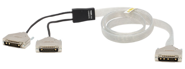 |
 |
|
| Description | Hi-Flex LD / TEC Cable for LCM100(/M) Mount |
Hi-Flex LD / TEC Cable for 10-Pin HHL Packages |
|
| Max Currenta | Pin A1, A2, A3, A4 | 11 A | 10 A |
| Pin 1, 2, 3, 4, 5 | 5 A | 5 A | |
| Connector Type | 17W2 Male and 13W3 Male to 9W4 Male |
17W2 Male and 13W3 Male to a Flat 10-Pin HHL Female Connector |
|
| Length | 1.5 m | 1.5 m | |
The CAB4007x connector cables for HHL laser packages are Hi-Flex™†, unshielded cables designed for high-current applications, where the laser diode (LD) and thermoelectric cooler (TEC) currents exceed most standard cable limits.
The CAB4007A cable connects the complete LCM100(/M) mount to ITC400xQCL series controllers via the 9W4 connector. The CAB4007B cable can connect any standard 10-Pin HHL laser directly to an ITC400xQCL series controller via the flat 10-Pin HHL female connector. The CAB4007B connector cable can be used with the LCM100(/M) mount when only the top cold plate is in use. For the pinout of the CAB4007A and CAB4007B cables, please see the Pin Diagrams tab.
Please pay attention to the controller specifications when the CAB4007A or CAB4007B connector cables are used with a controller other than the ITC400xQCL controllers to ensure that the cables will safely connect to the controller(s).
†Hi-Flex™ is a Trademark of Cicoil
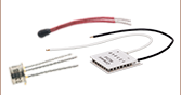
| Item # | CAB4005 | CON4005 |
|---|---|---|
| Click Image to Enlarge | 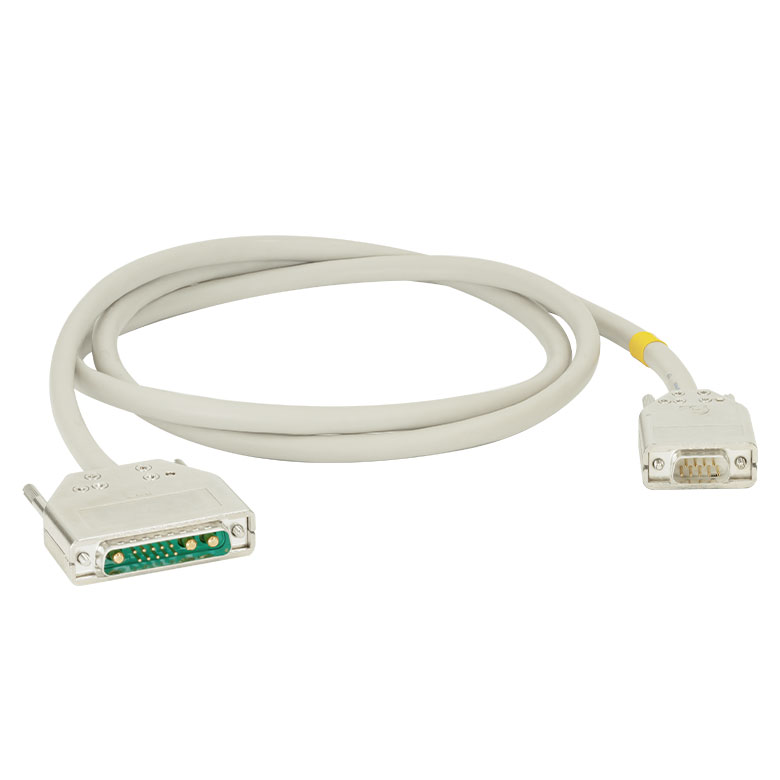 |
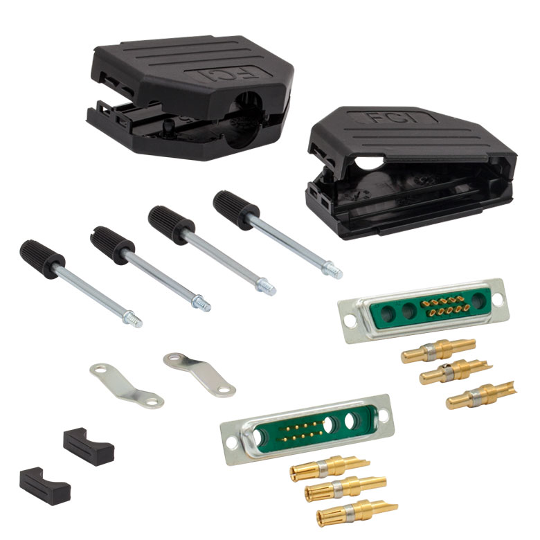 |
| Description | Standard Laser Diode Cable | 13W3 Male and Female Connector Kit (One Each) |
| Max Current | 5 A | 20 A |
| Connector Type | 13W3 Male to DB-9 Male | Loose 13W3 Connectors, Male and Female |
The CAB4005 cable connects our ITC4000 series dual current / temperature controllers to laser diode mounts. We also provide loose 13W3 connectors for customers who wish to make their own cables. Please see the Pin Diagrams tab for specific pinout information.
Please note that one CAB4005 cable and one CON4005 connector kit are included with the purchase of the ITC4002QCL and ITC4005QCL benchtop controllers (see the Shipping List tab for details).
| Item # | CAB4000 | CAB4001 | CON4001 |
|---|---|---|---|
| Click Image to Enlarge | 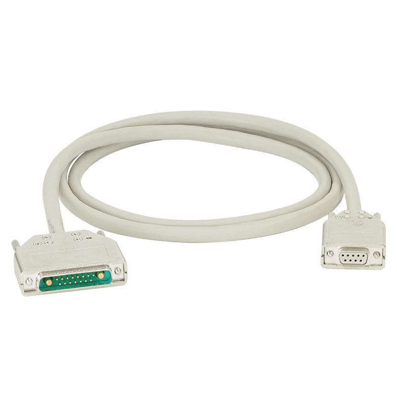 |
 |
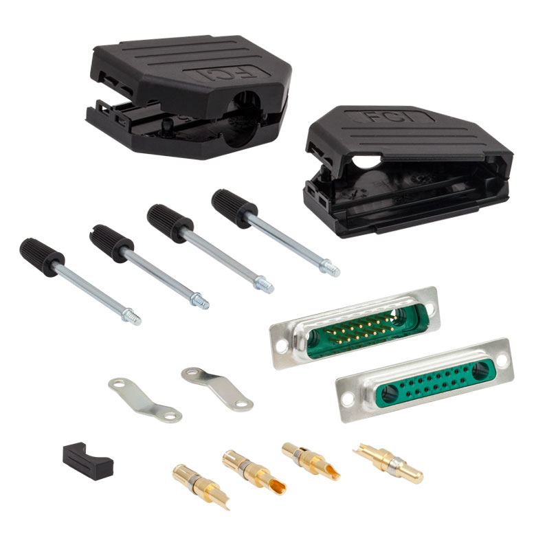 |
| Description | Standard TEC Element Cable | High Current TEC Element Cable | 17W2 Male and Female Connector Kit (One Each) |
| Max Current | 5 A | 20 A | 20 A |
| Connector Type | 17W2 Male to DB-9 Female | 17W2 Male to 17W2 Male | Loose 17W2 Connectors, Male and Female |
These cables connect ITC4000 series dual current / temperature controllers to thermoelectric cooling elements. We also provide loose 17W2 connectors for customers who wish to make their own cables. Please see the Pin Diagrams tab for specific pinout information.
Please note that one CAB4000 TEC cable is included with the purchase of an ITC4002QCL or ITC4005QCL controller. The CON4001 connector kit is included with all of the controllers (see the Shipping List tab for specific details).
| Calibration Service Item # | Compatible Controllers |
|---|---|
| CAL-ITC4 | ITC4001, ITC4002QCL, ITC4005, ITC4005QCL, ITC4020 |
Thorlabs offers recalibration services for our ITC4000 Series Combined Laser Diode and TEC Controllers. To ensure accurate measurements, we recommend recalibrating the devices every 24 months. The table to the right lists the controllers for which the CAL-ITC4 recalibration service is available.
Requesting a Calibration
Thorlabs provides two options for requesting a calibration:
- Complete the Returns Material Authorization (RMA) form. When completing the RMA form, please enter your name, contact information, the Part #, and the Serial # of the item being returned for calibration; in the Reason for Return field, select "I would like an item to be calibrated." All other fields are optional. Once the form has been submitted, a member of our RMA team will reach out to provide an RMA Number, return instructions, and to verify billing and payment information.
- Enter the Part # and Serial # of the item that requires recalbration below and then Add to Cart. A member of our RMA team will reach out to coordinate return of the item for calibration. Should you have other items in your cart, note that the calibration request will be split off from your order for RMA processing.
Please Note: To ensure your item being returned for calibration is routed appropriately once it arrives at our facility, please do not ship it prior to being provided an RMA Number and return instructions by a member of our team.