 Products Home / Lasers / Coherent Sources / Laser Diodes by Wavelength / Visible Laser Diodes: Center Wavelengths from 404 nm to 690 nm
Visible Laser Diodes: Center Wavelengths from 404 nm to 690 nm
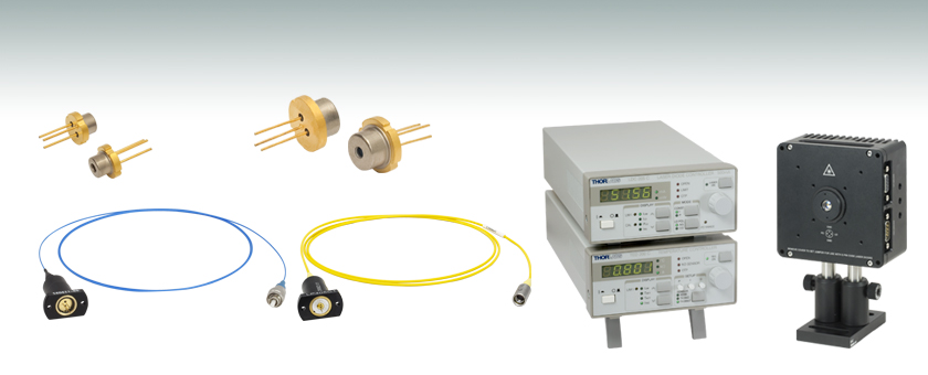
- Output Powers Up to 1600 mW
- Multiple Package Styles
- In-House Manufactured and Third-Party Options Available
Ø9 mm
Ø5.6 mm
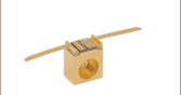
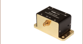
Pigtailed Laser Diode, PM Fiber
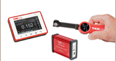
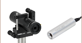
Application Idea
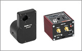
Our Laser Diode Driver Kits Include an
LD Controller, TEC Controller,
LD/TEC Mount, and Accessories
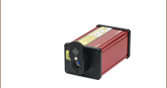
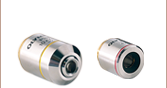
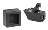
Pigtailed Laser Diode, SM Fiber with Collimated Output


Please Wait
| Laser Diode Selection Guidea |
|---|
| Shop by Wavelength |
| UV (375 nm) Visible (404 nm - 690 nm) NIR (705 nm - 2000 nm) MIR (4.05 µm - 11.00 µm) |
| Shop by Package / Type |
| Webpage Features | |
|---|---|
| Clicking this icon opens a window that contains specifications and mechanical drawings. | |
 |
Clicking this icon allows you to download our standard support documentation. |
|
Choose Item |
Clicking the words "Choose Item" opens a drop-down list containing all of the in-stock lasers around the desired center wavelength. The red icon next to the serial number then allows you to download L-I-V and spectral measurements for that serial-numbered device. |
Features
- Output Powers from 1 mW to 1600 mW
- Center Wavelengths Available from 404 nm to 690 nm
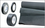
- Various Packages Available: TO Can and TO Pigtails
- Compatible with Thorlabs' Laser Diode and TEC Controllers
This webpage contains Thorlabs' laser diodes with center wavelengths from 404 nm to 690 nm. Diodes are arranged by wavelength and then power. The tables below list basic specifications to help you narrow down your search quickly. The blue button in the Info column within the tables opens a pop-up window that contains more detailed specifications for each item, as well as mechanical drawings.
Notes on Center Wavelength
While the center wavelength is listed for each laser diode, this is only a typical number. The center wavelength of a particular unit varies from production run to production run, so the diode you receive may not operate at the typical center wavelength. Diodes can be temperature tuned, which will alter the lasing wavelength. A number of items below are listed as Wavelength Tested, which means that the dominant wavelength of each unit has been measured and recorded. After clicking "Choose Item" below, a list will appear that contains the dominant wavelength, output power, and operating current of each in-stock unit. Clicking on the red Docs Icon next to the serial number provides access to a PDF with serial-number-specific L-I-V and spectral characteristics.
Packages and Mounts
We offer these visible laser diodes in various packages including standard Ø3.8 mm, Ø5.6 mm, and Ø9 mm TO cans, as well as TO-46, Ø9.5 mm, and fiber-pigtailed TO cans with outputs of either standard fiber connectors or collimators. We have categorized the pin configuration of TO-packaged diodes in standard A, B, C, D, E, F, G, and H pin codes (see image below). This pin code allows the user to easily determine compatible mounts.
Laser Mode and Linewidth
We offer laser diodes with different output characteristics (power, wavelength, beam size, shape, etc.). Most lasers offered here are single transverse mode (single mode or SM) and a few are designed for higher-power multiple-transverse-mode (multimode or MM) operation. For better side mode suppression ratio (SMSR) performance, other devices such as DFB lasers, DBR lasers, or external cavity lasers should be considered. Please see our Laser Diode Tutorial for more information on these topics and laser diodes in general.
Usage Tips
Laser diodes are sensitive to electrostatic shock. Please take the proper precautions when handling the device; see electrostatic shock accessories. These lasers are also sensitive to optical feedback, which can cause significant fluctuations in the output power of the laser diode depending on the application.
For all of the pigtailed laser diodes with fiber connectors at the output, the laser should be off when connecting or disconnecting the device from other fibers, particularly for lasers with power levels above 10 mW. We recommend cleaning the fiber connector before each use if there is any chance that dust or other contaminants may have deposited on the surface. The laser intensity at the center of the fiber tip can be very high and may burn the tip of the fiber if contaminants are present. While the connectors on the pigtailed laser diodes are cleaned and capped before shipping, we cannot guarantee that they will remain free of contamination after they are removed from the package.
Members of our Tech Support staff are available to help you select a laser diode and to discuss possible operation issues.
| Pin Code | Monitor Photodiode |
|---|---|
| A | Yes |
| B | Yes |
| C | Yes |
| D | Yes |
| E | No |
| F | Yes |
| G | No |
| H | No |
Choosing a Collimation Lens for Your Laser Diode
Since the output of a laser diode is highly divergent, collimating optics are necessary. Aspheric lenses do not introduce spherical aberration and are therefore are commonly chosen when the collimated laser beam is to be between one and five millimeters. A simple example will illustrate the key specifications to consider when choosing the correct lens for a given application. The second example below is an extension of the procedure, which will show how to circularize an elliptical beam.
Example 1: Collimating a Diverging Beam
- Laser Diode to be Used: L780P010
- Desired Collimated Beam Diameter: Ø3 mm (Major Axis)
When choosing a collimation lens, it is essential to know the divergence angle of the source being used and the desired output diameter. The specifications for the L780P010 laser diode indicate that the typical parallel and perpendicular FWHM beam divergences are 8° and 30°, respectively. Therefore, as the light diverges, an elliptical beam will result. To collect as much light as possible during the collimation process, consider the larger of these two divergence angles in any calculations (i.e., in this case, use 30°). If you wish to convert your elliptical beam into a round one, we suggest using an anamorphic prism pair, which magnifies one axis of your beam; for details, see Example 2 below.
Assuming that the thickness of the lens is small compared to the radius of curvature, the thin lens approximation can be used to determine the appropriate focal length for the asphere. Assuming a divergence angle of 30° (FWHM) and desired beam diameter of 3 mm:
 |
 |
||
| Θ = Divergence Angle | Ø = Beam Diameter | f = Focal Length | r = Collimated Beam Radius = Ø/2 |
Note that the focal length is generally not equal to the needed distance between the light source and the lens.
With this information known, it is now time to choose the appropriate collimating lens. Thorlabs offers a large selection of aspheric lenses. For this application, the ideal lens is a molded glass aspheric lens with focal length near 5.6 mm and our -B antireflection coating, which covers 780 nm. The C171TMD-B (mounted) or 354171-B (unmounted) aspheric lenses have a focal length of 6.20 mm, which will result in a collimated beam diameter (major axis) of 3.3 mm. Next, check to see if the numerical aperture (NA) of the diode is smaller than the NA of the lens:
0.30 = NALens > NADiode ≈ sin(15°) = 0.26
Up to this point, we have been using the full-width at half maximum (FWHM) beam diameter to characterize the beam. However, a better practice is to use the 1/e2 beam diameter. For a Gaussian beam profile, the 1/e2 diameter is almost equal to 1.7X the FWHM diameter. The 1/e2 beam diameter therefore captures more of the laser diode's output light (for greater power delivery) and minimizes far-field diffraction (by clipping less of the incident light).
A good rule of thumb is to pick a lens with an NA twice that of the laser diode NA. For example, either the A390-B or the A390TM-B could be used as these lenses each have an NA of 0.53, which is more than twice the approximate NA of our laser diode (0.26). These lenses each have a focal length of 4.6 mm, resulting in an approximate major beam diameter of 2.5 mm. In general, using a collimating lens with a short focal length will result in a small collimated beam diameter and a large beam divergence, while a lens with a large focal length will result in a large collimated beam diameter and a small divergence.
Example 2: Circularizing an Elliptical Beam
Using the laser diode and aspheric lens chosen above, we can use an anamorphic prism pair to convert our collimated, elliptical beam into a circular beam.
Whereas earlier we considered only the larger divergence angle, we now look at the smaller beam divergence of 8°. From this, and using the effective focal length of the A390-B aspheric lens chosen in Example 1, we can determine the length of the semi-minor axis of the elliptical beam after collimation:
r' = f * tan(Θ'/2) = 4.6 mm * tan(4°) = 0.32 mm
The minor beam diameter is double the semi-minor axis, or 0.64 mm. In order to magnify the minor diameter to be equal to the major diameter of 2.5 mm, we will need an anamorphic prism pair that yields a magnification of 3.9. Thorlabs offers both mounted and unmounted prism pairs. Mounted prism pairs provide the benefit of a stable housing to preserve alignment, while unmounted prism pairs can be positioned at any angle to achieve the exact desired magnification.
The PS883-B mounted prism pair provides a magnification of 4.0 for a 950 nm wavelength beam. Because shorter wavelengths undergo greater magnification when passing through the prism pair, we can expect our 780 nm beam to be magnified by slightly more than 4.0X. Thus, the beam will still maintain a small degree of ellipticity.
Alternatively, we can use the PS871-B unmounted prism pair to achieve the precise magnification of the minor diameter necessary to produce a circular beam. Using the data available here, we see that the PS871-B achieves a magnification of 4.0 when the prisms are positioned at the following angles for a 670 nm wavelength beam:
| α1: +34.608° | α2: -1.2455° |
Refer to the diagram to the right for α1 and α2 definitions. Our 780 nm laser will experience slightly less magnification than a 670 nm beam passing through the prisms at these angles. Some trial and error may be required to achieve the exact desired magnification. In general:
- To increase magnification, rotate the first prism clockwise (increasing α1) and rotate the second prism counterclockwise (decreasing α2).
- To reduce magnification, rotate the first prism counterclockwise (decreasing α1) and rotate the second prism clockwise (increasing α2).
Video Insight: Setting Up a TO Can Laser Diode
Installing a TO can laser diode in a mount and setting it up to run under temperature and current control presents many opportunities to make a mistake that could damage or destroy the laser. This step-by-step guide includes tips for keeping humans and laser diodes safe from harm.
When operated within their specifications, laser diodes have extremely long lifetimes. Most failures occur from mishandling or operating the lasers beyond their maximum ratings. Laser diodes are among the most static-sensitive devices currently made and proper ESD protection should be worn whenever handling a laser diode. Due to their extreme electrostatic sensitivity, laser diodes cannot be returned after their sealed package has been opened. Laser diodes in their original sealed package can be returned for a full refund or credit.
Handling and Storage Precautions
Because of their extreme susceptibility to damage from electrostatic discharge (ESD), care should be taken whenever handling and operating laser diodes.
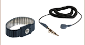
Wrist Straps
Use grounded anti-static wrist straps whenever handling diodes.
Anti-Static Mats
Always work on grounded anti-static mats.
Laser Diode Storage
When not in use, short the leads of the laser together to protect against ESD damage.
Operating and Safety Precautions
Use an Appropriate Driver
Laser diodes require precise control of operating current and voltage to avoid overdriving the laser. In addition, the laser driver should provide protection against power supply transients. Select a laser driver appropriate for your application. Do not use a voltage supply with a current-limiting resistor since it does not provide sufficient regulation to protect the laser diode.
Power Meters
When setting up and calibrating a laser diode with its driver, use a NIST-traceable power meter to precisely measure the laser output. It is usually safest to measure the laser diode output directly before placing the laser in an optical system. If this is not possible, be sure to take all optical losses (transmissive, aperture stopping, etc.) into consideration when determining the total output of the laser.
Reflections
Flat surfaces in the optical system in front of a laser diode can cause some of the laser energy to reflect back onto the laser’s monitor photodiode, giving an erroneously high photodiode current. If optical components are moved within the system and energy is no longer reflected onto the monitor photodiode, a constant-power feedback loop will sense the drop in photodiode current and try to compensate by increasing the laser drive current and possibly overdriving the laser. Back reflections can also cause other malfunctions or damage to laser diodes. To avoid this, be sure that all surfaces are angled 5-10°, and when necessary, use optical isolators to attenuate direct feedback into the laser.
Heat Sinks
Laser diode lifetime is inversely proportional to operating temperature. Always mount the laser diode in a suitable heat sink to remove excess heat from the laser package.
Voltage and Current Overdrive
Be careful not to exceed the maximum voltage and drive current listed on the specification sheet with each laser diode, even momentarily. Also, reverse voltages as little as 3 V can damage a laser diode.
ESD-Sensitive Device
Laser diodes are susceptible to ESD damage even during operation. This is particularly aggravated by using long interface cables between the laser diode and its driver due to the inductance that the cable presents. Avoid exposing the laser diode or its mounting apparatus to ESD at all times.
ON/OFF and Power-Supply-Coupled Transients
Due to their fast response times, laser diodes can be easily damaged by transients less than 1 µs. High-current devices such as soldering irons, vacuum pumps, and fluorescent lamps can cause large momentary transients, and thus surge-protected outlets should always be used when working with laser diodes.
If you have any questions regarding laser diodes, please contact Thorlabs Technical Support for assistance.
Laser Safety and Classification
Safe practices and proper usage of safety equipment should be taken into consideration when operating lasers. The eye is susceptible to injury, even from very low levels of laser light. Thorlabs offers a range of laser safety accessories that can be used to reduce the risk of accidents or injuries. Laser emission in the visible and near infrared spectral ranges has the greatest potential for retinal injury, as the cornea and lens are transparent to those wavelengths, and the lens can focus the laser energy onto the retina.
 |
 |
 |
 |
 |
 |
 |
 |
 |
Safe Practices and Light Safety Accessories
- Laser safety eyewear must be worn whenever working with Class 3 or 4 lasers.
- Regardless of laser class, Thorlabs recommends the use of laser safety eyewear whenever working with laser beams with non-negligible powers, since metallic tools such as screwdrivers can accidentally redirect a beam.
- Laser goggles designed for specific wavelengths should be clearly available near laser setups to protect the wearer from unintentional laser reflections.
- Goggles are marked with the wavelength range over which protection is afforded and the minimum optical density within that range.
- Laser Safety Curtains and Laser Safety Fabric shield other parts of the lab from high energy lasers.
- Blackout Materials can prevent direct or reflected light from leaving the experimental setup area.
- Thorlabs' Enclosure Systems can be used to contain optical setups to isolate or minimize laser hazards.
- A fiber-pigtailed laser should always be turned off before connecting it to or disconnecting it from another fiber, especially when the laser is at power levels above 10 mW.
- All beams should be terminated at the edge of the table, and laboratory doors should be closed whenever a laser is in use.
- Do not place laser beams at eye level.
- Carry out experiments on an optical table such that all laser beams travel horizontally.
- Remove unnecessary reflective items such as reflective jewelry (e.g., rings, watches, etc.) while working near the beam path.
- Be aware that lenses and other optical devices may reflect a portion of the incident beam from the front or rear surface.
- Operate a laser at the minimum power necessary for any operation.
- If possible, reduce the output power of a laser during alignment procedures.
- Use beam shutters and filters to reduce the beam power.
- Post appropriate warning signs or labels near laser setups or rooms.
- Use a laser sign with a lightbox if operating Class 3R or 4 lasers (i.e., lasers requiring the use of a safety interlock).
- Do not use Laser Viewing Cards in place of a proper Beam Trap.
Laser Classification
Lasers are categorized into different classes according to their ability to cause eye and other damage. The International Electrotechnical Commission (IEC) is a global organization that prepares and publishes international standards for all electrical, electronic, and related technologies. The IEC document 60825-1 outlines the safety of laser products. A description of each class of laser is given below:
| Class | Description | Warning Label |
|---|---|---|
| 1 | This class of laser is safe under all conditions of normal use, including use with optical instruments for intrabeam viewing. Lasers in this class do not emit radiation at levels that may cause injury during normal operation, and therefore the maximum permissible exposure (MPE) cannot be exceeded. Class 1 lasers can also include enclosed, high-power lasers where exposure to the radiation is not possible without opening or shutting down the laser. |  |
| 1M | Class 1M lasers are safe except when used in conjunction with optical components such as telescopes and microscopes. Lasers belonging to this class emit large-diameter or divergent beams, and the MPE cannot normally be exceeded unless focusing or imaging optics are used to narrow the beam. However, if the beam is refocused, the hazard may be increased and the class may be changed accordingly. | 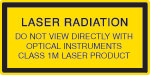 |
| 2 | Class 2 lasers, which are limited to 1 mW of visible continuous-wave radiation, are safe because the blink reflex will limit the exposure in the eye to 0.25 seconds. This category only applies to visible radiation (400 - 700 nm). | 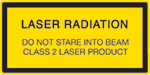 |
| 2M | Because of the blink reflex, this class of laser is classified as safe as long as the beam is not viewed through optical instruments. This laser class also applies to larger-diameter or diverging laser beams. |  |
| 3R | Class 3R lasers produce visible and invisible light that is hazardous under direct and specular-reflection viewing conditions. Eye injuries may occur if you directly view the beam, especially when using optical instruments. Lasers in this class are considered safe as long as they are handled with restricted beam viewing. The MPE can be exceeded with this class of laser; however, this presents a low risk level to injury. Visible, continuous-wave lasers in this class are limited to 5 mW of output power. |  |
| 3B | Class 3B lasers are hazardous to the eye if exposed directly. Diffuse reflections are usually not harmful, but may be when using higher-power Class 3B lasers. Safe handling of devices in this class includes wearing protective eyewear where direct viewing of the laser beam may occur. Lasers of this class must be equipped with a key switch and a safety interlock; moreover, laser safety signs should be used, such that the laser cannot be used without the safety light turning on. Laser products with power output near the upper range of Class 3B may also cause skin burns. |  |
| 4 | This class of laser may cause damage to the skin, and also to the eye, even from the viewing of diffuse reflections. These hazards may also apply to indirect or non-specular reflections of the beam, even from apparently matte surfaces. Great care must be taken when handling these lasers. They also represent a fire risk, because they may ignite combustible material. Class 4 lasers must be equipped with a key switch and a safety interlock. |  |
| All class 2 lasers (and higher) must display, in addition to the corresponding sign above, this triangular warning sign. |  |
|

Insights into Beam Characterization
Scroll down to read about:
- Beam Size Measurement Using a Chopper Wheel
Click here for more insights into lab practices and equipment.
Beam Size Measurement Using a Chopper Wheel
Click to Enlarge
Figure 2: The blade traces an arc length of Rθ through the center of the beam and has an angular rotation rate of  f. The chopper wheel shown is MC1F2.
Click to Enlarge
Figure 1: An approximate measurement of beam size can be found using the illustrated setup. As the blade of the chopper wheel passes through the beam, an S-curve is traced out on the oscilloscope.
Click to Enlarge
Figure 4: The diameter of a Gaussian beam is often given in terms of the 1/e2 full width.

Click to Enlarge
Figure 3: Rise time (tr ) of the intensity signal is typically measured between the 10% and 90% points on the curve. The rise time depends on the wheel's rotation rate and the beam diameter.
Camera and scanning-slit beam profilers are tools for characterizing beam size and shape, but these instruments cannot provide an accurate measurement if the beam size is too small or the wavelength is outside of the operating range.
A chopper wheel, photodetector, and oscilloscope can provide an approximate measurement of the beam size (Figure 1). As the rotating chopper wheel's blade passes through the beam, an S-shaped trace is displayed on the oscilloscope.
When the blade sweeps through the angle θ , the rise or fall time of the S-curve is proportional to the size of the beam along the direction of the blade's travel (Figure 2). A point on the blade located a distance R from the center of the wheel sweeps through an arc length (Rθ ) that is approximately equal to the size of the beam along this direction.
To make this beam size measurement, the combined response of the detector and oscilloscope should be much faster than the signal's rate of change.
Example: S-Curve with Rising Edge
The angle ftr )ftr )

includes a factor of 1.56, which accounts for the portion of the beam measured between the 10% and 90% intensity points being smaller than the 1/e2 beam diameter.
Date of Last Edit: June 22, 2021
Content improved by our readers!
| Posted Comments: | |
Zhang Chen
(posted 2024-01-03 14:31:40.733) Hi, What does it mean that the compliance voltage of LDC220C is greater than 4V??Could I use it to drive L450P1600MM with a working voltage of 4.8V?Thank you! jweimar
(posted 2024-01-09 03:49:56.0) Dear Zhang, thank you for your feedback. That means that the Compliance Voltage can be greater than 4V for smaller currents. I will reach out to you directly to discuss this further with you. Paulo Lourenço
(posted 2023-08-07 17:27:37.087) Hi there.
From what I understood, the LD PL450B requires an S038S package and is not compatible to strain relief cable. Will I still be able to use it with an LTN330-A collimation package? If so, what shall I use instead?
Thank you,
Paulo Lourenço ksosnowski
(posted 2023-08-18 06:05:17.0) Hello Paulo, thanks for reaching out to Thorlabs. Our LTN330-A collimator attachment is only designed to attach to the SR9x cables and our LDHx cageplates. The threading is an otherwise uncommon 13/32"-40TPI one to best fit these laser package sizes. While you are correct that we do not have an SR9 cable option for the 3.8mm size to match this, we do have some passive mounts like S1LM38 which can connect this diode format into an optic tube/cage system. However given the total electrical input power P=IV of your Pin Code G laser, I would strongly recommend use of an actively cooled mount like LDM38. Our LDMx series mounts have front mounting points to attach further optics like collimators as well. From there we also have mounts for different small asphere lens sizes like the one that comes in LTN330-A. Our lens adapter LMRA6.35 is a ring which the lens can be glued into to adapter the outer diameter to 1/2". This will allow mounting of the optic in standard 1/2" lens tubes or cageplates to connect with the laser diode. 大揮 松林
(posted 2023-01-12 09:52:03.457) L405G2の購入を検討しているのですが,このレーザーダイオードでコリメート光を作る場合どのレンズが適切でしょうか? cdolbashian
(posted 2023-01-23 11:40:46.0) Thank you for reaching out to us with this request! I have contacted you directly to assist in selecting components for your experimental design. D Miller
(posted 2021-06-02 19:40:59.217) Do you know the degree of polarization for L450P1600MM?
Thanks. YLohia
(posted 2021-06-15 11:05:59.0) Thank you for contacting Thorlabs. Unfortunately, we don't have a DOP spec for our laser diodes. That being said, the PER should be roughly 400:1, but this is not a formal spec either, but should serve as a reasonable estimate. Thibault Vieille
(posted 2019-11-18 01:35:10.207) Hi,
Try to set up a high power laser diode (visible betw. 500 and 700nm) with very high power stability. I see your laser driver LD3000R but it is written that it supports A, D and E pin config. However most of your most powerful laser diodes (L638P700M, L638P200, L637G1, L520G1 etc) comes with different pin config. Can you recommend me a correct fit; please? YLohia
(posted 2019-11-18 11:10:43.0) Hello, thank you for contacting Thorlabs. For these diodes, depending on the specific diode, we would recommend using the LDC220C driver. This provides up to +/-2 A current and is compatible with all of the diodes mentioned by you. rawoodruff
(posted 2018-09-15 10:30:46.96) What spectral width would you expect from your UV and visible diodes: single mode and multimode? YLohia
(posted 2018-09-24 11:32:11.0) Hello, thank you for contacting Thorlabs. We have linewidth test data for some of the diodes in the pigtailed laser diodes pages. Please note that these are Fabry-Perot diodes (with the exception of the DJ532) and cannot be used for single frequency applications. I have reached out to you directly to get a better sense of your application and what specific wavelengths you are interested in. paul.janin
(posted 2018-06-05 17:36:06.44) Hello, I've been trying to modulate an L637P5 with a square wave around threshold. However, the diode seems to respond too slowly to the modulation to follow the square wave even at frequencies as low as 10kHz. Do you know what could be the cause of this slow response ? The diode manages to follow a sine modulation even at higher frequencies, although with some attenuation. Thank you. YLohia
(posted 2018-07-27 03:24:04.0) Hello, thank you for contacting Thorlabs. Based on our discussion, the modulation bandwidth of the LDC201ULN driver you have is specified to be 3kHz. This bandwidth is only applicable to small signal sine wave modulation (not square wave). Another thing that can impact the bandwidth measurements is the terminating load resistance being used with your detector/oscilloscope. For fast measurements, a 50 Ohm load should be used (not 1 MOhm). vjadrisko
(posted 2017-05-19 14:03:07.04) Hi there, i am interested in laser diode LP660-SF20 but would like to know is it polarized and if so which polarization it is ? Thank you. tfrisch
(posted 2017-05-19 05:05:17.0) Hello, thank you for contacting Thorlabs. The light is polarized, but the state will be changed depending on bending and stressing of the SM fiber. We have fiber polarization management solutions in the link below. I will reach out to you to discuss these. https://www.thorlabs.com/navigation.cfm?guide_id=2089 ross.leyman
(posted 2015-05-13 17:45:00.44) Hi there,
Regarding the L520P120 - do you know what the beam diameter immediately at the diode package output window is? It looks like a clear aperture of 1.6mm but it's hard to tell of course.
Also, can this module be driven in pulse-mode operation or is it strictly CW only? And if pulse is ok, can a higher (peak) output power be achieved as one might expect?
Thanks in advance,
Ross besembeson
(posted 2015-08-28 10:42:41.0) Response from Bweh at Thorlabs USA: Our UK office will provide the beam diameter estimate at the window to you. We don't have modulation specifications for this diode, which is why we specify the diode under cw conditions. We don't also recommend pulsing at high peak powers. While the diode can in theory be pulsed, we recommend applying a DC bias current to threshold and pulsing above that. sinerkim
(posted 2014-01-24 08:37:01.07) Could you provide a LP520-SF15 without any fiber coupling? jacob.sendowski
(posted 2013-08-21 21:27:04.24) I would like to know the linewidth of this laser source. Also what time of temperature controlled mount would you recommend for operating this laser? thanks
Jdogg tcohen
(posted 2013-08-22 14:49:00.0) Response from Tim at Thorlabs: The linewidth of the LP785-SF100 is ~.5nm typical, max of 2nm. You can mount this with an LM9LP. We now show the individual tested datasheets corresponding to our current stock on our website. You can see measured spectrum by clicking the "Choose Item" link right next to the part number. In some cases, these plots will be limited to the spectral resolution of the spectrometer used. In this case, the spectrometer used has a resolution of <.6nm FWHM @633nm. saktinst
(posted 2013-06-18 16:05:00.883) I am going to use diode laser to mark my organic material. Do you have any idea what kind of laser can i use? Is it also this diode laser provided by scanning head to mark barcode code? Thanks jlow
(posted 2013-06-20 10:50:00.0) Response from Jeremy at Thorlabs: The correct laser to use would depend on the material that you are using and its absorption characteristic. I will get in contact with you directly to discuss about your application further. cristina.martinez-g
(posted 2013-04-17 10:16:47.623) Will be offered, in a near future, cheap lasers near 760nm ?
Thank you very much,
cristina tcohen
(posted 2013-04-25 12:57:00.0) Response from Tim at Thorlabs to Cristina: Thank you for your inquiry. We will take your feedback into consideration as we look to expand our wavelength selection and I will contact you directly to discuss your application. werneck
(posted 2013-04-07 21:04:57.74) 1) On datasheet of LPM-660-SMA it reads slope efficiency=0,75 mW/mA, output power=22.5 mW and operating current 65 mA. However, for a current of 65 mA with a slope efficiency of .75 it would produce an output power of 48.8mW not 22.5 mW as stated.
On the other hand, if I want 22 mW output power, from the slope efficiency I calculate 29 mA which is below the threshold current. What is wrong?
2) "Monitor current" is the output current of PD when LD is at maximum output power? jlow
(posted 2013-04-09 12:11:00.0) Response from Jeremy at Thorlabs: The slope efficiency is defined as ?P/?I and not P/I. The drive current below the threshold current of the laser diode does not contribute to light emission and therefore the slope is taken from the line in the laser power vs. current curve after the threshold current. In the characterization sheet sent with each laser diode pigtail, the monitor current is the current of the internal photodiode when the output is at 22mW. olsonaj
(posted 2013-03-16 17:51:31.903) Do you know if anyone has used the LD785-SH300 in an external cavity diode laser configuration?
Any reason why you believe it may or may not work in such a setup? jlow
(posted 2013-03-28 08:36:00.0) Response from Jeremy at Thorlabs: We do not have any data on using this laser diode in an external cavity. We will get in contact with you to discuss in more details about your application. Tyler
(posted 2012-07-31 17:52:43.0) Hello Florian,
The 1418 Euro price is based on what it cost Thorlabs to purchase the laser diodes in 2008. I am sorry that this hasn't been updated to be consistent with the current cost of laser diodes. Thank you for taking the time to point out the price of the DL3146-151 laser diode to us. I will work on getting the price of the diode fixed right away. Sincerely, Tyler florian.kehl
(posted 2012-07-27 02:47:49.0) Dear Sir or Madam,
we're frequent customers and so far happy with your products and service. But selling a DL3146-151 for 1418€ doesn't seem to be a fair price at all, since exactly the same product is being sold for only 18€, for example if you check: http://www.roithner-laser.com/pricelist.pdf.
How can this discrepancy be explained?
Thanks! tcohen
(posted 2012-04-03 10:46:00.0) Response from Tim at Thorlabs: Laser diodes can be delicate and require precise drive electronics. Because there is a maximum current which cannot be exceeded even for a very limited amount of time, spikes in electronics will cause immediate damage. Because a tiny change in voltage can be a large change in current, as seen on a LD’s I-V curve, temperature and other fluctuations in electronics when using a voltage source can cause the maximum drive current to be exceeded and damage the LD. For this reason, current sources are typically used. ZWJIORO
(posted 2012-03-30 02:17:48.0) Dear Thorlabs, could a voltage source drive the LD?Thanks! jjurado
(posted 2011-04-06 15:33:00.0) Response from Javier at Thorlabs to last poster: Thank you very much for your feedback. We will split the presentation of the L375P020MLD laser diode into another page in order to make it more visible. The new page will go live shortly. user
(posted 2011-04-06 08:26:24.0) L375P020MLD would get more attention if this group were titled NUV - Visible Laser Diodes Thorlabs
(posted 2010-08-31 13:51:26.0) Response from Javier at Thorlabs: Most of our laser diodes operate in single transverse mode and multi-longitudinal mode. Laser diodes are highly divergent sources, with a full angle output usually in the range of 30 degrees. You can refer to the Collimation Tutorial tab for information on how to choose the most appropriate optic for collimating the output of your laser. I will contact you directly to discuss your application. aroy25
(posted 2010-08-27 18:58:42.0) Are the single mode lasers also single transverse mode? I am looking for a TEM00 profile..what is the beam diameter?
regards Adam
(posted 2010-05-20 21:06:36.0) A response from Adam at Thorlabs to chenli: The laser diode controller, ITC510, has been superceded by the ITC4001. This product is a laser diode current and temperature controller, which can output of to 1A for laser diode current control and 8A for laser diode temperature control. I will contact you directly to determine the exact information that you need. chenli_hust
(posted 2010-05-20 19:31:03.0) I want to know some information about LASER DIODE COMBI CONTROLLER:ITC510,would you do me some help?
Im looking forward to your reply. Laurie
(posted 2010-03-29 17:37:27.0) A response from Laurie at Thorlabs to mph: Thank you for your feedback on our website. Currently, we are in the process of giving this page a makeover of sorts, so I am unable to make the suggested change visible to the general public immediately. However, we will be sure to include your suggested change in the new version of this page, which should be available in a few weeks. Thanks again for taking the time to provide valuable feedback! mph
(posted 2010-03-29 17:24:13.0) In the overview, you use `discreet incorrectly.
discreet:judicious in ones conduct or speech, esp. with regard to respecting privacy or maintaining silence about something of a delicate nature; prudent; circumspect.
You should change this to `discrete. klee
(posted 2009-07-17 15:33:25.0) A response from Ken at Thorlabs to alessandro: There is no direct replacement for the HL785MG. The closest alternatives in terms of wavelength and power are HL7851G (785nm, 50mW) and DL4140-001S (785nm, 25mW). alessandro
(posted 2009-07-17 13:26:24.0) Dear All,
What is the substitute of HL7859MG that was discontinued? klee
(posted 2009-06-22 18:58:36.0) Response from Ken at Thorlabs to BiryukovAA: We do not carry any green laser diodes but we do offer a few green HeNe lasers. BiryukovAA
(posted 2009-06-22 09:15:28.0) Our company is looking for Green Laser Diodes (543 nm). Can you offer any laser diodes operating on this wavelength.
thank you, Alexey Biryukov. j.velde
(posted 2009-03-17 06:11:13.0) What is the mode field dia on this LD?
Also do Thorlabs offer AR coated LD?
Thank you!
Jeroen van de Velde
Applied Laser Technology Laurie
(posted 2009-02-12 10:05:29.0) Response from Laurie at Thorlabs to dajun.wang: The HL6548FG is AR coated for the wavelength of the diode. We are in the process of trying to obtain more specific information and will update you shortly. dajun.wang
(posted 2009-02-09 19:06:13.0) Hi,
We bought some these HL6548FG 658 diodes from thorlabs for scientific research. One special thing is we want to put these diodes in an external cavity configuration to control the emission wavelength. Is it possible to let us know the coating material on the output facet of these diodes? We need to put additional anti-reflection coating on them by ourselves to help wavelength control.
Your help is highly appreciated.
With best wishes,
Dajun lsandstrom
(posted 2008-06-26 10:16:47.0) Are the lasers lateral or longitudinal multi-mode when you state in the spec. that the lasers are multi mode? technicalmarketing
(posted 2008-02-13 14:19:43.0) In response to acables comments, we have added a link to an excel file that shows the compatibility between our drivers and diodes. In the future, we hope to work with our web team to provide a selection. acable
(posted 2007-10-31 19:02:34.0) It would be nice to have a link to the laser diode and TEC drivers from this page. It would be even better to have a linked selection guide to show all of the options for each of the lasers. technicalmarketing
(posted 2007-10-22 08:34:05.0) Dear rodolfls, I apologize for the delay in getting this information to you. We had to pass your inquiry to our technical support staff in Japan, who then in turn had to contact the vendor. According to the vendor, the wavelength variation/current variation is about 0.04 nm/mA and the wavelength variation/temerature variation is about 0.2 nm/K. We hope that this information is helpful to you. rodolfls
(posted 2007-10-14 01:04:05.0) I would like to know some characteristics of Eudyna FLD6A2TK:
wavelenght variation/current variation = ? nm/mA and wavelenght variation/temperature variation = ? nm/K
Thank you,
Rodolfo. melsscal
(posted 2007-09-19 06:40:08.0) Dear Mr.Mark Struzzi,
Can you please mail me the catalouge Page of the laser diode L980P200J asap.
Regards
for MEL SYSTEMS & SERVICES LTD.
Aroop Kanti Bose
Area Manager-Sales
Kolkata Branch
www.melssindia.com |
| The rows shaded green below denote single-frequency lasers. |
| Item # | Wavelength | Output Power | Operating Current | Operating Voltage | Beam Divergence | Laser Mode | Package | |
|---|---|---|---|---|---|---|---|---|
| Parallel | Perpendicular | |||||||
| L375P70MLD | 375 nm | 70 mW | 110 mA | 5.4 V | 9° | 22.5° | Single Transverse Mode | Ø5.6 mm |
| L404P400M | 404 nm | 400 mW | 370 mA | 4.9 V | 13° (1/e2) | 42° (1/e2) | Multimode | Ø5.6 mm |
| LP405-SF10 | 405 nm | 10 mW | 50 mA | 5.0 V | - | - | Single Transverse Mode | Ø5.6 mm, SM Pigtail |
| L405P20 | 405 nm | 20 mW | 38 mA | 4.8 V | 8.5° | 19° | Single Transverse Mode | Ø5.6 mm |
| LP405C1 | 405 nm | 30 mW | 75 mA | 4.3 V | 1.4 mrad | 1.4 mrad | Single Transverse Mode | Ø3.8 mm, SM Pigtail with Collimator |
| L405G2 | 405 nm | 35 mW | 50 mA | 4.9 V | 10° | 21° | Single Transverse Mode | Ø3.8 mm |
| DL5146-101S | 405 nm | 40 mW | 70 mA | 5.2 V | 8° | 19° | Single Transverse Mode | Ø5.6 mm |
| L405A1 | 405 nm | 175 mW (Min) | 150 mA | 5.0 V | 9° | 20° | Single Transverse Mode | Ø5.6 mm |
| LP405-MF300 | 405 nm | 300 mW | 350 mA | 4.5 V | - | - | Multimode | Ø5.6 mm, MM Pigtail |
| L405G1 | 405 nm | 1000 mW | 900 mA | 5.0 V | 13° | 45° | Multimode | Ø9 mm |
| LP450-SF25 | 450 nm | 25 mW | 75 mA | 5.0 V | - | - | Single Transverse Mode | Ø5.6 mm, SM Pigtail |
| L450G3 | 450 nm | 100 mW (Min) | 80 mA | 5.2 V | 8.4° | 21.5° | Single Transverse Mode | Ø3.8 mm |
| L450G2 | 450 nm | 100 mW (Min) | 80 mA | 5.0 V | 8.4° | 21.5° | Single Transverse Mode | Ø5.6 mm |
| L450P1600MM | 450 nm | 1600 mW | 1200 mA | 4.8 V | 7° | 19 - 27° | Multimode | Ø5.6 mm |
| L473P100 | 473 nm | 100 mW | 120 mA | 5.7 V | 10 | 24 | Single Transverse Mode | Ø5.6 mm |
| LP488-SF20 | 488 nm | 20 mW | 70 mA | 6.0 V | - | - | Single Transverse Mode | Ø5.6 mm, SM Pigtail |
| LP488-SF20G | 488 nm | 20 mW | 80 mA | 5.5 V | - | - | Single Transverse Mode | Ø5.6 mm, SM Pigtail |
| L488P60 | 488 nm | 60 mW | 75 mA | 6.8 V | 7° | 23° | Single Transverse Mode | Ø5.6 mm |
| LP515-SF3 | 515 nm | 3 mW | 50 mA | 5.3 V | - | - | Single Transverse Mode | Ø5.6 mm, SM Pigtail |
| L515A1 | 515 nm | 10 mW | 50 mA | 5.4 V | 6.5° | 21° | Single Transverse Mode | Ø5.6 mm |
| LP520-SF15A | 520 nm | 15 mW | 100 mA | 7.0 V | - | - | Single Transverse Mode | Ø5.6 mm, SM Pigtail |
| LP520-SF15 | 520 nm | 15 mW | 140 mA | 6.5 V | - | - | Single Transverse Mode | Ø9 mm, SM Pigtail |
| L520A1 | 520 nm | 30 mW (Min) | 80 mA | 5.5 V | 8° | 22° | Single Transverse Mode | Ø5.6 mm |
| PL520 | 520 nm | 50 mW | 250 mA | 7.0 V | 7° | 22° | Single Transverse Mode | Ø3.8 mm |
| L520P50 | 520 nm | 45 mW | 150 mA | 7.0 V | 7° | 22° | Single Transverse Mode | Ø5.6 mm |
| L520A2 | 520 nm | 110 mW (Min) | 225 mA | 5.9 V | 8° | 22° | Single Transverse Mode | Ø5.6 mm |
| DJ532-10 | 532 nm | 10 mW | 220 mA | 1.9 V | 0.69° | 0.69° | Single Transverse Mode | Ø9.5 mm (non-standard) |
| DJ532-40 | 532 nm | 40 mW | 330 mA | 1.9 V | 0.69° | 0.69° | Single Transverse Mode | Ø9.5 mm (non-standard) |
| LP633-SF50 | 633 nm | 50 mW | 170 mA | 2.6 V | - | - | Single Transverse Mode | Ø5.6 mm, SM Pigtail |
| HL63163DG | 633 nm | 100 mW | 170 mA | 2.6 V | 8.5° | 18° | Single Transverse Mode | Ø5.6 mm |
| LPS-635-FC | 635 nm | 2.5 mW | 70 mA | 2.2 V | - | - | Single Transverse Mode | Ø9 mm, SM Pigtail |
| LPS-PM635-FC | 635 nm | 2.5 mW | 60 mA | 2.2 V | - | - | Single Transverse Mode | Ø9.0 mm, PM Pigtail |
| L635P5 | 635 nm | 5 mW | 30 mA | <2.7 V | 8° | 32° | Single Transverse Mode | Ø5.6 mm |
| HL6312G | 635 nm | 5 mW | 50 mA | <2.7 V | 8° | 31° | Single Transverse Mode | Ø9 mm |
| LPM-635-SMA | 635 nm | 8 mW | 50 mA | 2.2 V | - | - | Multimode | Ø9 mm, MM Pigtail |
| LP635-SF8 | 635 nm | 8 mW | 60 mA | 2.3 V | - | - | Single Transverse Mode | Ø5.6 mm, SM Pigtail |
| HL6320G | 635 nm | 10 mW | 60 mA | 2.2 V | 8° | 31° | Single Transverse Mode | Ø9 mm |
| HL6322G | 635 nm | 15 mW | 75 mA | 2.4 V | 8° | 30° | Single Transverse Mode | Ø9 mm |
| L637P5 | 637 nm | 5 mW | 20 mA | <2.4 V | 8° | 34° | Single Transverse Mode | Ø5.6 mm |
| LP637-SF50 | 637 nm | 50 mW | 140 mA | 2.6 V | - | - | Single Transverse Mode | Ø5.6 mm, SM Pigtail |
| LP637-SF70 | 637 nm | 70 mW | 220 mA | 2.7 V | - | - | Single Transverse Mode | Ø5.6 mm, SM Pigtail |
| HL63142DG | 637 nm | 100 mW | 140 mA | 2.7 V | 8° | 18° | Single Transverse Mode | Ø5.6 mm |
| HL63133DG | 637 nm | 170 mW | 250 mA | 2.8 V | 9° | 17° | Single Transverse Mode | Ø5.6 mm |
| HL6388MG | 637 nm | 250 mW | 340 mA | 2.3 V | 10° | 40° | Multimode | Ø5.6 mm |
| L637G1 | 637 nm | 1200 mW | 1100 mA | 2.5 V | 10° | 32° | Multimode | Ø9 mm (non-standard) |
| L638P040 | 638 nm | 40 mW | 92 mA | 2.4 V | 10° | 21° | Single Transverse Mode | Ø5.6 mm |
| L638P150 | 638 nm | 150 mW | 230 mA | 2.7 V | 9 | 18 | Single Transverse Mode | Ø3.8 mm |
| L638P200 | 638 nm | 200 mW | 280 mA | 2.9 V | 8 | 14 | Single Transverse Mode | Ø5.6 mm |
| L638P700M | 638 nm | 700 mW | 820 mA | 2.2 V | 9° | 35° | Multimode | Ø5.6 mm |
| HL6358MG | 639 nm | 10 mW | 40 mA | 2.4 V | 8° | 21° | Single Transverse Mode | Ø5.6 mm |
| HL6323MG | 639 nm | 30 mW | 100 mA | 2.5 V | 8.5° | 30° | Single Transverse Mode | Ø5.6 mm |
| HL6362MG | 640 nm | 40 mW | 90 mA | 2.5 V | 10° | 21° | Single Transverse Mode | Ø5.6 mm |
| LP642-SF20 | 642 nm | 20 mW | 90 mA | 2.5 V | - | - | Single Transverse Mode | Ø5.6 mm, SM Pigtail |
| LP642-PF20 | 642 nm | 20 mW | 90 mA | 2.5 V | - | - | Single Transverse Mode | Ø5.6 mm, PM Pigtail |
| HL6364DG | 642 nm | 60 mW | 120 mA | 2.5 V | 10° | 21° | Single Transverse Mode | Ø5.6 mm |
| HL6366DG | 642 nm | 80 mW | 150 mA | 2.5 V | 10° | 21° | Single Transverse Mode | Ø5.6 mm |
| HL6385DG | 642 nm | 150 mW | 250 mA | 2.6 V | 9° | 17° | Single Transverse Mode | Ø5.6 mm |
| L650P007 | 650 nm | 7 mW | 28 mA | 2.2 V | 9° | 28° | Single Transverse Mode | Ø5.6 mm |
| LPS-660-FC | 658 nm | 7.5 mW | 65 mA | 2.6 V | - | - | Single Transverse Mode | Ø5.6 mm, SM Pigtail |
| LP660-SF20 | 658 nm | 20 mW | 80 mA | 2.6 V | - | - | Single Transverse Mode | Ø5.6 mm, SM Pigtail |
| LPM-660-SMA | 658 nm | 22.5 mW | 65 mA | 2.6 V | - | - | Multimode | Ø5.6 mm, MM Pigtail |
| HL6501MG | 658 nm | 30 mW | 75 mA | 2.6 V | 8.5° | 22° | Single Transverse Mode | Ø5.6 mm |
| L658P040 | 658 nm | 40 mW | 75 mA | 2.2 V | 10° | 20° | Single Transverse Mode | Ø5.6 mm |
| LP660-SF40 | 658 nm | 40 mW | 135 mA | 2.5 V | - | - | Single Transverse Mode | Ø5.6 mm, SM Pigtail |
| LP660-SF60 | 658 nm | 60 mW | 210 mA | 2.4 V | - | - | Single Transverse Mode | Ø5.6 mm, SM Pigtail |
| HL6544FM | 660 nm | 50 mW | 115 mA | 2.3 V | 10° | 17° | Single Transverse Mode | Ø5.6 mm |
| LP660-SF50 | 660 nm | 50 mW | 140 mA | 2.3 V | - | - | Single Transverse Mode | Ø5.6 mm, SM Pigtail |
| HL6545MG | 660 nm | 120 mW | 170 mA | 2.45 V | 10° | 17° | Single Transverse Mode | Ø5.6 mm |
| L660P120 | 660 nm | 120 mW | 175 mA | 2.5 V | 10° | 17° | Single Transverse Mode | Ø5.6 mm |
| L670VH1 | 670 nm | 1 mW | 2.5 mA | 2.6 V | 10° | 10° | Single Transverse Mode | TO-46 |
| LPS-675-FC | 670 nm | 2.5 mW | 55 mA | 2.2 V | - | - | Single Transverse Mode | Ø9 mm, SM Pigtail |
| HL6748MG | 670 nm | 10 mW | 30 mA | 2.2 V | 8° | 25° | Single Transverse Mode | Ø5.6 mm |
| HL6714G | 670 nm | 10 mW | 55 mA | <2.7 V | 8° | 22° | Single Transverse Mode | Ø9 mm |
| HL6756MG | 670 nm | 15 mW | 35 mA | 2.3 V | 8° | 24° | Single Transverse Mode | Ø5.6 mm |
| LP685-SF15 | 685 nm | 15 mW | 55 mA | 2.1 V | - | - | Single Transverse Mode | Ø5.6 mm, SM Pigtail |
| HL6750MG | 685 nm | 50 mW | 70 mA | 2.3 V | 9° | 21° | Single Transverse Mode | Ø5.6 mm |
| HL6738MG | 690 nm | 30 mW | 85 mA | 2.5 V | 8.5° | 19° | Single Transverse Mode | Ø5.6 mm |
| LP705-SF15 | 705 nm | 15 mW | 55 mA | 2.3 V | - | - | Single Transverse Mode | Ø5.6 mm, SM Pigtail |
| HL7001MG | 705 nm | 40 mW | 75 mA | 2.5 V | 9° | 18° | Single Transverse Mode | Ø5.6 mm |
| LP730-SF15 | 730 nm | 15 mW | 70 mA | 2.5 V | - | - | Single Transverse Mode | Ø5.6 mm, SM Pigtail |
| HL7302MG | 730 nm | 40 mW | 75 mA | 2.5 V | 9° | 18° | Single Transverse Mode | Ø5.6 mm |
| L760VH1 | 760 nm | 0.5 mW | 3 mA (Max) | 2.2 V | 12° | 12° | Single Frequency | TO-46 |
| DBR760PN | 761 nm | 9 mW | 125 mA | 2.0 V | - | - | Single Frequency | Butterfly, PM Pigtail |
| L763VH1 | 763 nm | 0.5 mW | 3 mA (Max) | 2.0 V | 10° | 10° | Single Frequency | TO-46 |
| DBR767PN | 767 nm | 23 mW | 220 mA | 1.87 V | - | - | Single Frequency | Butterfly, PM Pigtail |
| DBR770PN | 770 nm | 35 mW | 220 mA | 1.92 V | - | - | Single Frequency | Butterfly, PM Pigtail |
| L780P010 | 780 nm | 10 mW | 24 mA | 1.8 V | 8° | 30° | Single Transverse Mode | Ø5.6 mm |
| LP780-SAD15 | 780 nm | 15 mW | 180 mA | 2.2 V | - | - | Single Frequency | Ø9 mm, SM Pigtail |
| DBR780PN | 780 nm | 45 mW | 250 mA | 1.9 V | - | - | Single Frequency | Butterfly, PM Pigtail |
| L785P5 | 785 nm | 5 mW | 28 mA | 1.9 V | 10° | 29° | Single Transverse Mode | Ø5.6 mm |
| LPS-PM785-FC | 785 nm | 6.5 mW | 60 mA | - | - | - | Single Transverse Mode | Ø5.6 mm, PM Pigtail |
| LPS-785-FC | 785 nm | 10 mW | 65 mA | 1.85 V | - | - | Single Transverse Mode | Ø5.6 mm, SM Pigtail |
| LP785-SF20 | 785 nm | 20 mW | 85 mA | 1.9 V | - | - | Single Transverse Mode | Ø5.6 mm, SM Pigtail |
| DBR785S | 785 nm | 25 mW | 230 mA | 2.0 V | - | - | Single Frequency | Butterfly, SM Pigtail |
| DBR785P | 785 nm | 25 mW | 230 mA | 2.0 V | - | - | Single Frequency | Butterfly, PM Pigtail |
| L785P25 | 785 nm | 25 mW | 45 mA | 1.9 V | 8° | 30° | Single Transverse Mode | Ø5.6 mm |
| FPV785S | 785 nm | 50 mW | 410 mA | 2.2 V | - | - | Single Frequency | Butterfly, SM Pigtail |
| FPV785P | 785 nm | 50 mW | 410 mA | 2.1 V | - | - | Single Frequency | Butterfly, PM Pigtail |
| LP785-SAV50 | 785 nm | 50 mW | 500 mA | 2.2 V | - | - | Single Frequency | Ø9 mm, SM Pigtail |
| L785P090 | 785 nm | 90 mW | 125 mA | 2.0 V | 10° | 17° | Single Transverse Mode | Ø5.6 mm |
| LP785-SF100 | 785 nm | 100 mW | 300 mA | 2.0 V | - | - | Single Transverse Mode | Ø9 mm, SM Pigtail |
| FPL785P | 785 nm | 200 mW | 500 mA | 2.1 V | - | - | Single Transverse Mode | Butterfly, PM Pigtail |
| FPL785S-250 | 785 nm | 250 mW (Min) | 500 mA | 2.0 V | - | - | Single Transverse Mode | Butterfly, SM Pigtail |
| LD785-SEV300 | 785 nm | 300 mW | 500 mA (Max) | 2.0 V | 8° | 16° | Single Frequency | Ø9 mm |
| LD785-SH300 | 785 nm | 300 mW | 400 mA | 2.0 V | 7° | 18° | Single Transverse Mode | Ø9 mm |
| FPL785C | 785 nm | 300 mW | 400 mA | 2.0 V | 7° | 18° | Single Transverse Mode | 3 mm x 5 mm Submount |
| LD785-SE400 | 785 nm | 400 mW | 550 mA | 2.0 V | 7° | 16° | Single Transverse Mode | Ø9 mm |
| FPV785M | 785 nm | 600 mW | 1100 mA | 1.9 V | - | - | Multimode | Butterfly, MM Pigtail |
| L795VH1 | 795 nm | 0.25 mW | 1.2 mA | 1.8 V | 20° | 12° | Single Frequency | TO-46 |
| DBR795PN | 795 nm | 40 mW | 230 mA | 2.0 V | - | - | Single Frequency | Butterfly, PM Pigtail |
| DBR808PN | 808 nm | 42 mW | 250 mA | 2 V | - | - | Single Frequency | Butterfly, PM Pigtail |
| LP808-SA60 | 808 nm | 60 mW | 150 mA | 1.9 V | - | - | Single Transverse Mode | Ø9 mm, SM Pigtail |
| M9-808-0150 | 808 nm | 150 mW | 180 mA | 1.9 V | 8° | 17° | Single Transverse Mode | Ø9 mm |
| L808P200 | 808 nm | 200 mW | 260 mA | 2 V | 10° | 30° | Multimode | Ø5.6 mm |
| FPL808P | 808 nm | 200 mW | 600 mA | 2.1 V | - | - | Single Transverse Mode | Butterfly, PM Pigtail |
| FPL808S | 808 nm | 200 mW | 750 mA | 2.3 V | - | - | Single Transverse Mode | Butterfly, SM Pigtail |
| L808H1 | 808 nm | 300 mW | 400 mA | 2.1 V | 14° | 6° | Single Transverse Mode | Ø9 mm |
| LD808-SE500 | 808 nm | 500 mW | 750 mA | 2.2 V | 7° | 14° | Single Transverse Mode | Ø9 mm |
| LD808-SEV500 | 808 nm | 500 mW | 800 mA (Max) | 2.2 V | 8° | 14° | Single Frequency | Ø9 mm |
| L808P500MM | 808 nm | 500 mW | 650 mA | 1.8 V | 12° | 30° | Multimode | Ø5.6 mm |
| L808P1000MM | 808 nm | 1000 mW | 1100 mA | 2 V | 9° | 30° | Multimode | Ø9 mm |
| DBR816PN | 816 nm | 45 mW | 250 mA | 1.95 V | - | - | Single Frequency | Butterfly, PM Pigtail |
| LP820-SF80 | 820 nm | 80 mW | 230 mA | 2.3 V | - | - | Single Transverse Mode | Ø5.6 mm, SM Pigtail |
| L820P100 | 820 nm | 100 mW | 145 mA | 2.1 V | 9° | 17° | Single Transverse Mode | Ø5.6 mm |
| L820P200 | 820 nm | 200 mW | 250 mA | 2.4 V | 9° | 17° | Single Transverse Mode | Ø5.6 mm |
| DBR828PN | 828 nm | 24 mW | 250 mA | 2.0 V | - | - | Single Frequency | Butterfly, PM Pigtail |
| LPS-830-FC | 830 nm | 10 mW | 120 mA | - | - | - | Single Transverse Mode | Ø5.6 mm, SM Pigtail |
| LPS-PM830-FC | 830 nm | 10 mW | 120 mA | - | - | - | Single Transverse Mode | Ø5.6 mm, PM Pigtail |
| LP830-SF30 | 830 nm | 30 mW | 115 mA | 1.9 V | - | - | Single Transverse Mode | Ø9 mm, SM Pigtail |
| HL8338MG | 830 nm | 50 mW | 75 mA | 1.9 V | 9° | 22° | Single Transverse Mode | Ø5.6 mm |
| L830H1 | 830 nm | 250 mW | 3 A (Max) | 2 V | 8° | 10° | Single Transverse Mode | Ø9 mm |
| FPL830P | 830 nm | 300 mW | 900 mA | 2.22 V | - | - | Single Transverse Mode | Butterfly, PM Pigtail |
| FPL830S | 830 nm | 350 mW | 900 mA | 2.5 V | - | - | Single Transverse Mode | Butterfly, SM Pigtail |
| LD830-SE650 | 830 nm | 650 mW | 900 mA | 2.3 V | 7° | 13° | Single Transverse Mode | Ø9 mm |
| LD830-MA1W | 830 nm | 1 W | 2 A | 2.1 V | 7° | 24° | Multimode | Ø9 mm |
| LD830-ME2W | 830 nm | 2 W | 3 A (Max) | 2.0 V | 8° | 21° | Multimode | Ø9 mm |
| L840P200 | 840 nm | 200 mW | 255 mA | 2.4 V | 9 | 17 | Single Transverse Mode | Ø5.6 mm |
| L850VH1 | 850 nm | 1 mW | 6 mA (Max) | 2 V | 12° | 12° | Single Frequency | TO-46 |
| L850P010 | 850 nm | 10 mW | 50 mA | 2 V | 10° | 30° | Single Transverse Mode | Ø5.6 mm |
| L850P030 | 850 nm | 30 mW | 65 mA | 2 V | 8.5° | 30° | Single Transverse Mode | Ø5.6 mm |
| FPV852S | 852 nm | 20 mW | 400 mA | 2.2 V | - | - | Single Frequency | Butterfly, SM Pigtail |
| FPV852P | 852 nm | 20 mW | 400 mA | 2.2 V | - | - | Single Frequency | Butterfly, PM Pigtail |
| DBR852PN | 852 nm | 24 mW | 300 mA | 2.0 V | - | - | Single Frequency | Butterfly, PM Pigtail |
| LP852-SF30 | 852 nm | 30 mW | 115 mA | 1.9 V | - | - | Single Transverse Mode | Ø9 mm, SM Pigtail |
| L852P50 | 852 nm | 50 mW | 75 mA | 1.9 V | 9° | 22° | Single Transverse Mode | Ø5.6 mm |
| LP852-SF60 | 852 nm | 60 mW | 150 mA | 2.0 V | - | - | Single Transverse Mode | Ø9 mm, SM Pigtail |
| L852P100 | 852 nm | 100 mW | 120 mA | 1.9 V | 8° | 28° | Single Transverse Mode | Ø9 mm |
| L852P150 | 852 nm | 150 mW | 170 mA | 1.9 V | 8° | 18° | Single Transverse Mode | Ø9 mm |
| L852SEV1 | 852 nm | 270 mW | 400 mA (Max) | 2.0 V | 9° | 12° | Single Frequency | Ø9 mm |
| L852H1 | 852 nm | 300 mW | 415 mA (Max) | 2 V | 7° | 15° | Single Transverse Mode | Ø9 mm |
| FPL852P | 852 nm | 300 mW | 900 mA | 2.35 V | - | - | Single Transverse Mode | Butterfly, PM Pigtail |
| FPL852S | 852 nm | 350 mW | 900 mA | 2.5 V | - | - | Single Transverse Mode | Butterfly, SM Pigtail |
| LD852-SE600 | 852 nm | 600 mW | 950 mA | 2.3 V | 7° (1/e2) | 13° (1/e2) | Single Transverse Mode | Ø9 mm |
| LD852-SEV600 | 852 nm | 600 mW | 1050 mA (Max) | 2.2 V | 8° | 13° (1/e2) | Single Frequency | Ø9 mm |
| LP880-SF3 | 880 nm | 3 mW | 25 mA | 2.2 V | - | - | Single Transverse Mode | Ø5.6 mm, SM Pigtail |
| L880P010 | 880 nm | 10 mW | 30 mA | 2.0 V | 12° | 37° | Single Transverse Mode | Ø5.6 mm |
| L895VH1 | 895 nm | 0.2 mW | 1.4 mA | 1.6 V | 20° | 13° | Single Frequency | TO-46 |
| DBR895PN | 895 nm | 12 mW | 300 mA | 2 V | - | - | Single Frequency | Butterfly, PM Pigtail |
| LP904-SF3 | 904 nm | 3 mW | 30 mA | 1.5 V | - | - | Single Transverse Mode | Ø5.6 mm, SM Pigtail |
| L904P010 | 904 nm | 10 mW | 50 mA | 2.0 V | 10° | 30° | Single Transverse Mode | Ø5.6 mm |
| LP915-SF40 | 915 nm | 40 mW | 130 mA | 1.5 V | - | - | Single Transverse Mode | Ø9 mm, SM Pigtail |
| DBR935PN | 935 nm | 13 mW | 300 mA | 1.75 V | - | - | Single Frequency | Butterfly, PM Pigtail |
| LP940-SF30 | 940 nm | 30 mW | 90 mA | 1.5 V | - | - | Single Transverse Mode | Ø9 mm, SM Pigtail |
| M9-940-0200 | 940 nm | 200 mW | 270 mA | 1.9 V | 8° | 28° | Single Transverse Mode | Ø9 mm |
| L960H1 | 960 nm | 250 mW | 400 mA | 2.1 V | 11° | 12° | Single Transverse Mode | Ø9 mm |
| FPV976S | 976 nm | 30 mW | 400 mA (Max) | 2.2 V | - | - | Single Frequency | Butterfly, SM Pigtail |
| FPV976P | 976 nm | 30 mW | 400 mA (Max) | 2.2 V | - | - | Single Frequency | Butterfly, PM Pigtail |
| DBR976PN | 976 nm | 33 mW | 450 mA | 2.0 V | - | - | Single Frequency | Butterfly, PM Pigtail |
| L976SEV1 | 976 nm | 270 mW | 400 mA (Max) | 2.0 V | 9° | 12° | Single Frequency | Ø9 mm |
| BL976-SAG3 | 976 nm | 300 mW | 470 mA | 2.0 V | - | - | Single Transverse Mode | Butterfly, SM Pigtail |
| BL976-PAG500 | 976 nm | 500 mW | 830 mA | 2.0 V | - | - | Single Transverse Mode | Butterfly, PM Pigtail |
| BL976-PAG700 | 976 nm | 700 mW | 1090 mA | 2.0 V | - | - | Single Transverse Mode | Butterfly, PM Pigtail |
| BL976-PAG900 | 976 nm | 900 mW | 1480 mA | 2.5 V | - | - | Single Transverse Mode | Butterfly, PM Pigtail |
| L980P010 | 980 nm | 10 mW | 25 mA | 2 V | 10° | 30° | Single Transverse Mode | Ø5.6 mm |
| LP980-SF15 | 980 nm | 15 mW | 70 mA | 1.5 V | - | - | Single Transverse Mode | Ø5.6 mm, SM Pigtail |
| L980P030 | 980 nm | 30 mW | 50 mA | 1.5 V | 10° | 35° | Single Transverse Mode | Ø5.6 mm |
| L980P100A | 980 nm | 100 mW | 150 mA | 1.6 V | 6° | 32° | Multimode | Ø5.6 mm |
| LP980-SA60 | 980 nm | 60 mW | 230 mA | 2.0 V | - | - | Single Transverse Mode | Ø9.0 mm, SM Pigtail |
| LP980-SA100 | 980 nm | 100 mW | 180 mA | 1.5 V | - | - | Single Transverse Mode | Ø5.6 mm, SM Pigtail |
| L980H1 | 980 nm | 200 mW | 300 mA (Max) | 2.0 V | 8° | 13° | Single Transverse Mode | Ø9 mm |
| L980P200 | 980 nm | 200 mW | 300 mA | 1.5 V | 6° | 30° | Multimode | Ø5.6 mm |
| DBR1060SN | 1060 nm | 130 mW | 650 mA | 2.0 V | - | - | Single Frequency | Butterfly, SM Pigtail |
| DBR1060PN | 1060 nm | 130 mW | 650 mA | 1.8 V | - | - | Single Frequency | Butterfly, PM Pigtail |
| DBR1064S | 1064 nm | 40 mW | 150 mA | 2.0 V | - | - | Single Frequency | Butterfly, SM Pigtail |
| DBR1064P | 1064 nm | 40 mW | 150 mA | 2.0 V | - | - | Single Frequency | Butterfly, PM Pigtail |
| DBR1064PN | 1064 nm | 110 mW | 550 mA | 2.0 V | - | - | Single Frequency | Butterfly, PM Pigtail |
| LPS-1060-FC | 1064 nm | 50 mW | 220 mA | 1.4 V | - | - | Single Transverse Mode | Ø9 mm, SM Pigtail |
| M9-A64-0200 | 1064 nm | 200 mW | 280 mA | 1.7 V | 8° | 28° | Single Transverse Mode | Ø9 mm |
| L1064H1 | 1064 nm | 300 mW | 700 mA | 1.92 V | 7.6° | 13.5° | Single Transverse Mode | Ø9 mm |
| L1064H2 | 1064 nm | 450 mW | 1100 mA | 1.92 V | 7.6° | 13.5° | Single Transverse Mode | Ø9 mm |
| DBR1083PN | 1083 nm | 100 mW | 500 mA | 1.75 V | - | - | Single Frequency | Butterfly, PM Pigtail |
| L1270P5DFB | 1270 nm | 5 mW | 15 mA | 1.1 V | 7° | 9° | Single Frequency | Ø5.6 mm |
| L1290P5DFB | 1290 nm | 5 mW | 16 mA | 1.0 V | 7° | 9° | Single Frequency | Ø5.6 mm |
| LP1310-SAD2 | 1310 nm | 2.0 mW | 40 mA | 1.1 V | - | - | Single Frequency | Ø5.6 mm, SM Pigtail |
| LP1310-PAD2 | 1310 nm | 2.0 mW | 40 mA | 1.0 V | - | - | Single Frequency | Ø5.6 mm, PM Pigtail |
| LPS-1310-FC | 1310 nm | 2.5 mW | 20 mA | 1.1 V | - | - | Single Transverse Mode | Ø5.6 mm, SM Pigtail |
| LPS-PM1310-FC | 1310 nm | 2.5 mW | 20 mA | 1.1 V | - | - | Single Transverse Mode | Ø5.6 mm, PM Pigtail |
| L1310P5DFB | 1310 nm | 5 mW | 16 mA | 1.0 V | 7° | 9° | Single Frequency | Ø5.6 mm |
| ML725B8F | 1310 nm | 5 mW | 20 mA | 1.1 V | 25° | 30° | Single Transverse Mode | Ø5.6 mm |
| LPSC-1310-FC | 1310 nm | 50 mW | 350 mA | 2 V | - | - | Single Transverse Mode | Ø5.6 mm, SM Pigtail |
| FPL1053S | 1310 nm | 130 mW | 400 mA | 1.7 V | - | - | Single Transverse Mode | Butterfly, SM Pigtail |
| FPL1053P | 1310 nm | 130 mW | 400 mA | 1.7 V | - | - | Single Transverse Mode | Butterfly, PM Pigtail |
| FPL1053T | 1310 nm | 300 mW (Pulsed) | 750 mA | 2 V | 15° | 28° | Single Transverse Mode | Ø5.6 mm |
| FPL1053C | 1310 nm | 300 mW (Pulsed) | 750 mA | 2 V | 15° | 27° | Single Transverse Mode | Chip on Submount |
| L1310G1 | 1310 nm | 2000 mW | 5 A | 1.5 V | 7° | 24° | Multimode | Ø9 mm |
| L1330P5DFB | 1330 nm | 5 mW | 14 mA | 1.0 V | 7° | 9° | Single Frequency | Ø5.6 mm |
| L1370G1 | 1370 nm | 2000 mW | 5 A | 1.4 V | 6° | 22° | Multimode | Ø9 mm |
| BL1425-PAG500 | 1425 nm | 500 mW | 1600 mA | 2.0 V | - | - | Single Transverse Mode | Butterfly, PM Pigtail |
| BL1436-PAG500 | 1436 nm | 500 mW | 1600 mA | 2.0 V | - | - | Single Transverse Mode | Butterfly, PM Pigtail |
| L1450G1 | 1450 nm | 2000 mW | 5 A | 1.4 V | 7° | 22° | Multimode | Ø9 mm |
| BL1456-PAG500 | 1456 nm | 500 mW | 1600 mA | 2.0 V | - | - | Single Transverse Mode | Butterfly, PM Pigtail |
| L1470P5DFB | 1470 nm | 5 mW | 19 mA | 1.0 V | 7° | 9° | Single Frequency | Ø5.6 mm |
| L1480G1 | 1480 nm | 2000 mW | 5 A | 1.6 V | 6° | 20° | Multimode | Ø9 mm |
| L1490P5DFB | 1490 nm | 5 mW | 24 mA | 1.0 V | 7° | 9° | Single Frequency | Ø5.6 mm |
| L1510P5DFB | 1510 nm | 5 mW | 20 mA | 1.0 V | 7° | 9° | Single Frequency | Ø5.6 mm |
| L1530P5DFB | 1530 nm | 5 mW | 21 mA | 1.0 V | 7° | 9° | Single Frequency | Ø5.6 mm |
| LPS-1550-FC | 1550 nm | 1.5 mW | 30 mA | 1.0 V | - | - | Single Transverse Mode | Ø5.6 mm, SM Pigtail |
| LPS-PM1550-FC | 1550 nm | 1.5 mW | 30 mA | 1.1 V | - | - | Single Transverse Mode | Ø5.6 mm, SM Pigtail |
| LP1550-SAD2 | 1550 nm | 2.0 mW | 40 mA | 1.0 V | - | - | Single Frequency | Ø5.6 mm, SM Pigtail |
| LP1550-PAD2 | 1550 nm | 2.0 mW | 40 mA | 1.0 V | - | - | Single Frequency | Ø5.6 mm, PM Pigtail |
| L1550P5DFB | 1550 nm | 5 mW | 20 mA | 1.0 V | 8° | 10° | Single Frequency | Ø5.6 mm |
| ML925B45F | 1550 nm | 5 mW | 30 mA | 1.1 V | 25° | 30° | Single Transverse Mode | Ø5.6 mm |
| SFL1550S | 1550 nm | 40 mW | 300 mA | 1.5 V | - | - | Single Frequency | Butterfly, SM Pigtail |
| SFL1550P | 1550 nm | 40 mW | 300 mA | 1.5 V | - | - | Single Frequency | Butterfly, PM Pigtail |
| LPSC-1550-FC | 1550 nm | 50 mW | 250 mA | 2 V | - | - | Single Transverse Mode | Ø5.6 mm, SM Pigtail |
| FPL1009S | 1550 nm | 100 mW | 400 mA | 1.4 V | - | - | Single Transverse Mode | Butterfly, SM Pigtail |
| FPL1009P | 1550 nm | 100 mW | 400 mA | 1.4 V | - | - | Single Transverse Mode | Butterfly, PM Pigtail |
| ULN15PC | 1550 nm | 140 mW | 650 mA | 3.0 V | - | - | Single Frequency | Extended Butterfly, PM Pigtail |
| ULN15PT | 1550 nm | 140 mW | 650 mA | 3.0 V | - | - | Single Frequency | Extended Butterfly, PM Pigtail |
| FPL1001C | 1550 nm | 150 mW | 400 mA | 1.4 V | 18° | 31° | Single Transverse Mode | Chip on Submount |
| FPL1055T | 1550 nm | 300 mW (Pulsed) | 750 mA | 2 V | 15° | 28° | Single Transverse Mode | Ø5.6 mm |
| FPL1055C | 1550 nm | 300 mW (Pulsed) | 750 mA | 2 V | 15° | 28° | Single Transverse Mode | Chip on Submount |
| L1550G1 | 1550 nm | 1700 mW | 5 A | 1.5 V | 7° | 28° | Multimode | Ø9 mm |
| DFB1550 | 1555 nm | 100 mW (Min) | 1000 mA (Max) | 3.0 V | - | - | Single Frequency | Butterfly, SM Pigtail |
| DFB1550P | 1555 nm | 100 mW (Min) | 1000 mA (Max) | 3.0 V | - | - | Single Frequency | Butterfly, PM Pigtail |
| L1570P5DFB | 1570 nm | 5 mW | 25 mA | 1.0 V | 7° | 9° | Single Frequency | Ø5.6 mm |
| L1575G1 | 1575 nm | 1700 mW | 5 A | 1.5 V | 6° | 28° | Multimode | Ø9 mm |
| LPSC-1625-FC | 1625 nm | 50 mW | 350 mA | 1.5 V | - | - | Single Transverse Mode | Ø5.6 mm, SM Pigtail |
| FPL1054S | 1625 nm | 80 mW | 400 mA | 1.7 V | - | - | Single Transverse Mode | Butterfly, SM Pigtail |
| FPL1054P | 1625 nm | 80 mW | 400 mA | 1.7 V | - | - | Single Transverse Mode | Butterfly, PM Pigtail |
| FPL1054C | 1625 nm | 250 mW (Pulsed) | 750 mA | 2 V | 15° | 28° | Single Transverse Mode | Chip on Submount |
| FPL1054T | 1625 nm | 200 mW (Pulsed) | 750 mA | 2 V | 15° | 28° | Single Transverse Mode | Ø5.6 mm |
| FPL1059S | 1650 nm | 80 mW | 400 mA | 1.7 V | - | - | Single Transverse Mode | Butterfly, SM Pigtail |
| FPL1059P | 1650 nm | 80 mW | 400 mA | 1.7 V | - | - | Single Transverse Mode | Butterfly, PM Pigtail |
| FPL1059C | 1650 nm | 225 mW (Pulsed) | 750 mA | 2 V | 15° | 28° | Single Transverse Mode | Chip on Submount |
| FPL1059T | 1650 nm | 225 mW (Pulsed) | 750 mA | 2 V | 15° | 28° | Single Transverse Mode | Ø5.6 mm |
| FPL1940S | 1940 nm | 15 mW | 400 mA | 2 V | - | - | Single Transverse Mode | Butterfly, SM Pigtail |
| FPL2000S | 2 µm | 15 mW | 400 mA | 2 V | - | - | Single Transverse Mode | Butterfly, SM Pigtail |
| FPL2000C | 2 µm | 30 mW | 400 mA | 5.2 V | 8° | 19° | Single Transverse Mode | Chip on Submount |
| ID3250HHLH | 3.00 - 3.50 µm (DFB) | 5 mW | 400 mA (Max) | 5 V | 6 mrad (0.34°) | 6 mrad (0.34°) | Single Frequency | Two-Tab C-Mount |
| QF3850T1 | 3.85 µm (FP) | 200 mW | 600 mA (Max) | 13.5 V | 30° | 40° | Single Transverse Mode | Ø9 mm |
| QF3850HHLH | 3.85 µm (FP) | 320 mW (Min) | 1100 mA (Max) | 13 V | 6 mrad (0.34°) | 6 mrad (0.34°) | Single Transverse Mode | Horizontal HHL |
| QF4040HHLH | 4.05 µm (FP) | 320 mW (Min) | 1100 mA (Max) | 13 V | 6 mrad (0.34°) | 6 mrad (0.34°) | Single Transverse Mode | Horizontal HHL |
| QD4500CM1 | 4.00 - 5.00 µm (DFB) | 40 mW | 500 mA (Max) | 10.5 V | 30° | 40° | Single Frequency | Two-Tab C-Mount |
| QF4050T2 | 4.05 µm (FP) | 70 mW | 250 mA | 12 V | 30° | 40° | Single Transverse Mode | Ø9 mm |
| QF4050C2 | 4.05 µm (FP) | 300 mW | 400 mA | 12 V | 30 | 42 | Single Transverse Mode | Two-Tab C-Mount |
| QF4050T1 | 4.05 µm (FP) | 300 mW | 600 mA (Max) | 12.0 V | 30° | 40° | Single Transverse Mode | Ø9 mm |
| QF4050D2 | 4.05 µm (FP) | 800 mW | 750 mA | 13 V | 30° | 40° | Single Transverse Mode | D-Mount |
| QF4050D3 | 4.05 µm (FP) | 1200 mW | 1000 mA | 13 V | 30° | 40° | Single Transverse Mode | D-Mount |
| QD4472HH | 4.472 µm (DFB) | 85 mW | 500 mA (Max) | 11 V | 6 mrad (0.34°) | 6 mrad (0.34°) | Single Frequency | Horizontal HHL |
| QF4600T2 | 4.60 µm (FP) | 200 mW | 500 mA (Max) | 13.0 V | 30° | 40° | Single Transverse Mode | Ø9 mm |
| QF4600T1 | 4.60 µm (FP) | 400 mW | 800 mA (Max) | 12.0 V | 30° | 40° | Single Transverse Mode | Ø9 mm |
| QF4600C2 | 4.60 µm (FP) | 600 mW | 600 mA | 12 V | 30° | 42° | Single Transverse Mode | Two-Tab C-Mount |
| QF4600T3 | 4.60 µm (FP) | 1000 mW | 800 mA (Max) | 13 V | 30° | 40° | Single Transverse Mode | Ø9 mm |
| QF4600D4 | 4.60 µm (FP) | 2500 mW | 1800 mA | 12.5 V | 40° | 30° | Single Transverse Mode | D-Mount |
| QF4600D3 | 4.60 µm (FP) | 3000 mW | 1700 mA | 12.5 V | 30° | 40° | Single Transverse Mode | D-Mount |
| QD4602HH | 4.602 µm (DFB) | 150 mW | 1000 mA (Max) | 12 V | 6 mrad (0.34°) | 6 mrad (0.34°) | Single Frequency | Horizontal HHL |
| QF4650HHLH | 4.65 µm (FP) | 1500 mW (Min) | 1100 mA | 12 V | 6 mrad (0.34°) | 6 mrad (0.34°) | Single Transverse Mode | Horizontal HHL |
| QD5500CM1 | 5.00 - 6.00 µm (DFB) | 40 mW | 700 mA (Max) | 9.5 V | 30° | 45° | Single Frequency | Two-Tab C-Mount |
| QD5250C2 | 5.20 - 5.30 µm (DFB) | 60 mW | 700 mA (Max) | 9.5 V | 30° | 45° | Single Frequency | Two-Tab C-Mount |
| QD5263HH | 5.263 µm (DFB) | 130 mW | 1000 mA (Max) | 12 V | 6 mrad (0.34°) | 6 mrad (0.34°) | Single Frequency | Horizontal HHL |
| QD6500CM1 | 6.00 - 7.00 µm (DFB) | 40 mW | 650 mA (Max) | 10 V | 35° | 50° | Single Frequency | Two-Tab C-Mount |
| QD6134HH | 6.134 µm (DFB) | 50 mW | 1000 mA (Max) | 12 V | 6 mrad (0.34°) | 6 mrad (0.34°) | Single Frequency | Horizontal HHL |
| QD7500CM1 | 7.00 - 8.00 µm (DFB) | 40 mW | 600 mA (Max) | 10 V | 40° | 50° | Single Frequency | Two-Tab C-Mount |
| QD7500HHLH | 7.00 - 8.00 µm (DFB) | 50 mW | 700 mA (Max) | 12 V | 6 mrad (0.34°) | 6 mrad (0.34°) | Single Frequency | Horizontal HHL |
| QD7500DM1 | 7.00 - 8.00 µm (DFB) | 100 mW | 600 mA (Max) | 11.5 V | 40° | 55° | Single Frequency | D-Mount |
| QD7416HH | 7.416 µm (DFB) | 100 mW | 1000 mA (Max) | 12 V | 6 mrad (0.34°) | 6 mrad (0.34°) | Single Frequency | Horizontal HHL |
| QD7716HH | 7.716 µm (DFB) | 30 mW | 1000 mA (Max) | 12 V | 6 mrad (0.34°) | 6 mrad (0.34°) | Single Frequency | Horizontal HHL |
| QF7900HB | 7.9 µm (FP) | 700 mW | 1600 mA (Max) | 9 V | 6 mrad (0.34°) | 6 mrad (0.34°) | Single Transverse Mode | Horizontal HHL |
| QD7901HH | 7.901 µm (DFB) | 50 mW | 700 mA (Max) | 10 V | 6 mrad (0.34°) | 6 mrad (0.34°) | Single Frequency | Horizontal HHL |
| QD8050CM1 | 8.00 - 8.10 µm (DFB) | 100 mW | 1000 mA (Max) | 9.5 V | 55° | 70° | Single Frequency | Two-Tab C-Mount |
| QD8500CM1 | 8.00 - 9.00 µm (DFB) | 100 mW | 900 mA (Max) | 9.5 V | 40° | 55° | Single Frequency | Two-Tab C-Mount |
| QD8500HHLH | 8.00 - 9.00 µm (DFB) | 100 mW | 600 mA (Max) | 10.2 V | 6 mrad (0.34°) | 6 mrad (0.34°) | Single Frequency | Horizontal HHL |
| QF8450C2 | 8.45 µm (FP) | 300 mW | 750 mA | 9 V | 40° | 60° | Single Transverse Mode | Two-Tab C-Mount |
| QF8500HB | 8.5 µm (FP) | 500 mW | 2000 mA (Max) | 9 V | 6 mrad (0.34°) | 6 mrad (0.34°) | Single Transverse Mode | Horizontal HHL |
| QD8650CM1 | 8.60 - 8.70 µm (DFB) | 50 mW | 900 mA (Max) | 9.5 V | 55° | 70° | Single Frequency | Two-Tab C-Mount |
| QD8912HH | 8.912 µm (DFB) | 150 mW | 1000 mA (Max) | 12 V | 6 mrad (0.34°) | 6 mrad (0.34°) | Single Frequency | Horizontal HHL |
| QD9500CM1 | 9.00 - 10.00 µm (DFB) | 60 mW | 800 mA (Max) | 9.5 V | 40° | 55° | Single Frequency | Two-Tab C-Mount |
| QD9500HHLH | 9.00 - 10.00 µm (DFB) | 100 mW | 600 mA (Max) | 10.2 V | 6 mrad (0.34°) | 6 mrad (0.34°) | Single Frequency | Horizontal HHL |
| QD9062HH | 9.062 µm (DFB) | 130 mW | 1000 mA (Max) | 12 V | 6 mrad (0.34°) | 6 mrad (0.34°) | Single Frequency | Horizontal HHL |
| QF9150C2 | 9.15 µm (FP) | 200 mW | 850 mA | 11 V | 40° | 60° | Single Transverse Mode | Two-Tab C-Mount |
| QF9200HB | 9.2 µm (FP) | 250 mW | 2000 mA (Max) | 9 V | 6 mrad (0.34°) | 6 mrad (0.34°) | Single Transverse Mode | Horizontal HHL |
| QF9500T1 | 9.5 µm (FP) | 300 mW | 550 mA | 12 V | 40° | 55° | Single Transverse Mode | Ø9 mm |
| QD9550C2 | 9.50 - 9.60 µm (DFB) | 60 mW | 800 mA (Max) | 9.5 V | 40° | 55° | Single Frequency | Two-Tab C-Mount |
| QF9550CM1 | 9.55 µm (FP) | 80 mW | 1500 mA | 7.8 V | 35° | 60° | Single Transverse Mode | Two-Tab C-Mount |
| QD9697HH | 9.697 µm (DFB) | 80 mW | 1000 mA (Max) | 12 V | 6 mrad (0.34°) | 6 mrad (0.34°) | Single Frequency | Horizontal HHL |
| QD10500CM1 | 10.00 - 11.00 µm (DFB) | 40 mW | 600 mA (Max) | 10 V | 40° | 55° | Single Frequency | Two-Tab C-Mount |
| QD10500HHLH | 10.00 - 11.00 µm (DFB) | 50 mW | 700 mA (Max) | 12 V | 6 mrad (0.34°) | 6 mrad (0.34°) | Single Frequency | Horizontal HHL |
| QD10530HH | 10.530 µm (DFB) | 50 mW | 1000 mA (Max) | 12 V | 6 mrad (0.34°) | 6 mrad (0.34°) | Single Frequency | Horizontal HHL |
| QD10549HH | 10.549 µm (DFB) | 60 mW | 1000 mA (Max) | 12 V | 6 mrad (0.34°) | 6 mrad (0.34°) | Single Frequency | Horizontal HHL |
| QD10622HH | 10.622 µm (DFB) | 60 mW | 1000 mA (Max) | 12 V | 6 mrad (0.34°) | 6 mrad (0.34°) | Single Frequency | Horizontal HHL |
| The rows shaded green above denote single-frequency lasers. |
| Item # | Info | Wavelength (nm) |
Power (mW)a,b |
Typical/Max Drive Currenta |
Package | Pin Code | Monitor Photodiodec |
Compatible Socket |
Wavelength Tested |
Laser Mode |
|---|---|---|---|---|---|---|---|---|---|---|
| L404P400M | 404 | 400 | 370 mA / 410 mA | Ø5.6 mm | G | No | S7060R | No | Multimode | |
| LP405-SF10 | 405 | 10 | 50 mA / 60 mA | Ø5.6 mm, SM Pigtail | B | Yes | S7060Rd | Yes | Single Transverse Mode | |
| L405P20 | 405 | 20 | 38 mA / 55 mA | Ø5.6 mm | B | Yes | S7060R | No | Single Transverse Mode | |
| LP405C1 | 405 | 30 | 75 mA / 110 mA | Ø3.8 mm, SM Pigtail, Collimator Output |
G | No | S038Sd | Yes | Single Transverse Mode | |
| L405G2e | 405 | 35 | 50 mA / 75 mA | Ø3.8 mm | G | No | S038S | Yes | Single Transverse Mode | |
| DL5146-101S | 405 | 40 | 70 mA / 100 mA | Ø5.6 mm | B | Yes | S7060R | No | Single Transverse Mode | |
| L405A1 | 405 | 175 (Min) | 150 mA / 200 mA | Ø5.6 mm | A | Yes | S7060R | No | Single Transverse Mode | |
| LP405-MF300 | 405 | 300 | 350 mA / 410 mA | Ø5.6 mm, MM Pigtail | G | No | S7060Rd | Yes | Multimode | |
| L405G1 | 405 | 1000 | 900 mA / 1200 mA | Ø9 mm | G | No | S8060 | No | Multimode |
| Item # | Info | Wavelength (nm) |
Power (mW)a,b |
Typical/Max Drive Currenta |
Package | Pin Code |
Monitor Photodiodec |
Compatible Socket |
Wavelength Tested |
Laser Mode |
|---|---|---|---|---|---|---|---|---|---|---|
| LP450-SF25 | 450 | 25 | 75 mA / 140 mA | Ø5.6 mm, SM Pigtail | G | No | S7060Rd | Yes | Single Transverse Mode | |
| L450G3 | 450 | 100 (Min) | 80 mA / 110 mA | Ø3.8 mm | G | No | S038S | No | Single Transverse Mode | |
| L450G2 | 450 | 100 (Min) | 80 mA / 110 mA | Ø5.6 mm | G | No | S7060R | No | Single Transverse Mode | |
| L450P1600MM | 450 | 1600 | 1200 mA / 1500 mA | Ø5.6 mm | G | No | S7060R | No | Multimode | |
| L473P100 | 473 | 100 | 120 mA / 150 mA | Ø5.6 mm | F+e | Yes | - | No | Single Transverse Mode | |
| LP488-SF20 | 488 | 20 | 85 mA / 110 mA | Ø5.6 mm, SM Pigtail | B | Yes | S7060Rd | Yes | Single Transverse Mode | |
| LP488-SF20G | 488 | 20 | 80 mA / 120 mA | Ø5.6 mm, SM Pigtail | G | No | S7060Rd | Yes | Single Transverse Mode | |
| L488P60 | 488 | 60 | 75 mA / 110 mA | Ø5.6 mm | B | Yes | S7060R | No | Single Transverse Mode |
| Item # | Info | Wavelength (nm) |
Power (mW)a,b |
Typical/Max Drive Currenta |
Package | Pin Code | Monitor Photodiodec |
Compatible Socket |
Wavelength Tested |
Laser Mode |
|---|---|---|---|---|---|---|---|---|---|---|
| LP515-SF3 | 515 | 3 | 50 mA / 100 mA | Ø5.6 mm, SM Pigtail | A | Yes | S7060Rd | Yes | Single Transverse Mode | |
| L515A1 | 515 | 10 | 50 mA / 100 mA | Ø5.6 mm | A | Yes | S7060R | No | Single Transverse Mode | |
| LP520-SF15A | 520 | 15 | 100 mA / 160 mA | Ø5.6 mm, SM Pigtail | A | Yes | S7060Rd | Yes | Single Transverse Mode | |
| L520A1 | 520 | 30 (Min) | 80 mA / 100 mA | Ø5.6 mm | A | No | S7060R | No | Single Transverse Mode | |
| PL520 | 520 | 50 | 150 mA / 160 mA | Ø3.8 mm | G | No | S038S | No | Single Transverse Mode | |
| L520P50 | 520 | 50 | 150 mA / 160 mA | Ø5.6 mm | A | Yes | S7060R | No | Single Transverse Mode | |
| L520A2 | 520 | 110 (Min) | 225 mA / 330 mA | Ø5.6 mm | A | No | S7060R | No | Single Transverse Mode |
| Item # | Info | Wavelength (nm) |
Power (mW)a |
Typical/Max Drive Currenta |
Package | Pin Code | Monitor Photodiode |
Compatible Socket |
Wavelength Tested |
Laser Mode |
|---|---|---|---|---|---|---|---|---|---|---|
| DJ532-10b | 532 | 10 | 220 mA / 250 mA | Ø9.5 mm (non-standard)c | A | Yesd | - | No | Single Transverse Mode | |
| DJ532-40b | 532 | 40 | 330 mA / 400 mA | Ø9.5 mm (non-standard)c | E | No | - | No | Single Transverse Mode |
| Item # | Info | Wavelength (nm) |
Power (mW)a |
Typical/Max Drive Currenta |
Package | Pin Code |
Monitor Photodiodeb |
Compatible Socket |
Wavelength Tested |
Laser Mode |
|---|---|---|---|---|---|---|---|---|---|---|
| LP633-SF50 | 633 | 50 | 170 mA / 210 mA | Ø5.6 mm SM Pigtail, FC/PC | G | No | S7060Rc | Yes | Single Transverse Mode | |
| HL63163DG | 633 | 100 | 170 mA / 230 mA | Ø5.6 mm | G | No | S7060R | No | Single Transverse Mode | |
| LPS-635-FC | 635 | 2.5 | 70 mA / 95 mA | Ø9 mm, SM Pigtail | A | Yes | S8060 or S8060-4 | Yes | Single Transverse Mode | |
| LPS-PM635-FC | 635 | 2.5 | 60 mA / 95 mA | Ø9.0 mm, PM Pigtaild | A | Yes | S8060 or S8060-4 | Yes | Single Transverse Mode | |
| L635P5 | 635 | 5 | 30 mA / 45 mA | Ø5.6 mm | A | Yes | S7060R | No | Single Transverse Mode | |
| HL6312G | 635 | 5 | 50 mA / 85 mA | Ø9 mm | A | Yes | S8060 or S8060-4 | No | Single Transverse Mode | |
| LPM-635-SMA | 635 | 7.5 | 70 mA / 95 mA | Ø9 mm, MM Pigtail | A | Yes | S8060 or S8060-4 | Yes | Multimodee | |
| LP635-SF8 | 635 | 8 | 85 mA / 100 mA | Ø5.6 mm, SM Pigtail | A | Yes | S7060Rc | Yes | Single Transverse Mode | |
| HL6320G | 635 | 10 | 60 mA / 95 mA | Ø9 mm | A | Yes | S8060 or S8060-4 | No | Single Transverse Mode | |
| HL6322G | 635 | 15 | 75 mA / 100 mA | Ø9 mm | A | Yes | S8060 or S8060-4 | No | Single Transverse Mode |
| Item # | Info | Wavelength (nm) |
Power (mW)a |
Typical/Max Drive Currenta |
Package | Pin Code | Monitor Photodiodeb |
Compatible Socket |
Wavelength Tested |
Laser Mode |
|---|---|---|---|---|---|---|---|---|---|---|
| L637P5 | 637 | 5 | 20 mA / 25 mA | Ø5.6 mm | C | Yes | S7060R | No | Single Transverse Mode | |
| LP637-SF50 | 637 | 50 | 140 mA / 180 mA | Ø5.6 mm, SM Pigtail | A | Yes | S7060Rc | Yes | Single Transverse Mode | |
| LP637-SF70 | 637 | 70 | 220 mA / 300 mA | Ø5.6 mm, SM Pigtail | G | No | S7060Rc | Yes | Single Transverse Mode | |
| HL63142DG | 637 | 100 | 140 mA / 180 mA | Ø5.6 mm | A | Yes | S7060R | No | Single Transverse Mode | |
| HL63133DG | 637 | 170 | 250 mA / 320 mA | Ø5.6 mm | G | No | S7060R | No | Single Transverse Mode | |
| HL6388MG | 637 | 250 | 340 mA / 430 mA | Ø5.6 mm | H | No | S7060R | No | Multimode | |
| L637G1 | 637 | 1200 | 1100 mA / 1500 mA | Ø9 mmd | G | No | Customd | No | Multimode | |
| L638P040 | 638 | 40 | 92 mA / 115 mA | Ø5.6 mm | A | Yes | S7060R | No | Single Transverse Mode | |
| L638P150 | 638 | 150 | 230 mA / 300 mA | Ø3.8 mm | G | No | S038S | No | Single Transverse Mode | |
| L638P200 | 638 | 200 | 280 mA / 330 mA | Ø5.6 mm | G | No | S7060R | No | Single Transverse Mode | |
| L638P700M | 638 | 700 | 820 mA / 1000 mA | Ø5.6 mm | G | No | S7060R | No | Multimode | |
| HL6358MG | 639 | 10 | 40 mA / 50 mA | Ø5.6 mm | A | Yes | S7060R | No | Single Transverse Mode | |
| HL6323MG | 639 | 30 | 100 mA / 130 mA | Ø5.6 mm | A | Yes | S7060R | No | Single Transverse Mode |
| Item # | Info | Wavelength (nm) |
Power (mW)a |
Typical/Max Drive Currenta |
Package | Pin Code | Monitor Photodiodeb |
Compatible Socket |
Wavelength Tested |
Laser Mode |
|---|---|---|---|---|---|---|---|---|---|---|
| HL6362MG | 640 | 40 | 90 mA / 110 mA | Ø5.6 mm | A | Yes | S7060R | No | Single Transverse Mode | |
| LP642-SF20 | 642 | 20 | 90 mA / 140 mA | Ø5.6 mm, SM Pigtail | A | Yes | S7060Rc | Yes | Single Transverse Mode | |
| LP642-PF20 | 642 | 20 | 90 mA / 150 mA | Ø5.6 mm, PM Pigtaild | A | Yes | S7060Rc | Yes | Single Transverse Mode | |
| HL6364DG | 642 | 60 | 120 mA / 155 mA | Ø5.6 mm | A | Yes | S7060R | No | Single Transverse Mode | |
| HL6366DG | 642 | 80 | 150 mA / 175 mA | Ø5.6 mm | A | Yes | S7060R | No | Single Transverse Mode | |
| HL6385DG | 642 | 150 | 250 mA / 350 mA | Ø5.6 mm | H | No | S7060R | No | Single Transverse Mode |
| Item # | Info | Wavelength (nm) |
Power (mW)a |
Typical/Max Drive Currenta |
Package | Pin Code | Monitor Photodiodeb |
Compatible Socket |
Wavelength Tested |
Laser Mode |
|---|---|---|---|---|---|---|---|---|---|---|
| L650P007 | 650 | 7 | 28 mA / 35 mA | Ø5.6 mm | A | Yes | S7060R | No | Single Transverse Mode | |
| LPS-660-FC | 658 | 7.5 | 65 mA / 95 mA | Ø5.6 mm, SM Pigtail | C | Yes | S7060Rc | Yes | Single Transverse Mode | |
| LP660-SF20 | 658 | 20 | 80 mA / 110 mA | Ø5.6 mm, SM Pigtail | A | Yes | S7060Rc | Yes | Single Transverse Mode | |
| LPM-660-SMA | 658 | 22.5 | 65 mA / 95 mA | Ø5.6 mm, MM Pigtail | C | Yes | S7060Rc | Yes | Multimoded | |
| HL6501MG | 658 | 30 | 75 mA / 120 mA | Ø5.6 mm | C | Yes | S7060R | No | Single Transverse Mode | |
| L658P040 | 658 | 40 | 75 mA / 110 mA | Ø5.6 mm | A | Yes | S7060R | No | Single Transverse Mode | |
| LP660-SF40 | 658 | 40 | 135 mA / 170 mA | Ø5.6 mm, SM Pigtail | H | No | S7060Rc | Yes | Single Transverse Mode | |
| LP660-SF60 | 658 | 60 | 210 mA / 250 mA | Ø5.6 mm, SM Pigtail | H | No | S7060Rc | Yes | Single Transverse Mode |
| Item # | Info | Wavelength (nm) |
Power (mW)a |
Typical/Max Drive Currenta |
Package | Pin Code | Monitor Photodiodeb |
Compatible Socket |
Wavelength Tested |
Laser Mode |
|---|---|---|---|---|---|---|---|---|---|---|
| HL6544FM | 660 | 50 | 115 mA / 135 mA | Ø5.6 mm | G | No | S7060R | No | Single Transverse Mode | |
| LP660-SF50 | 660 | 50 | 140 mA / 200 mA | Ø5.6 mm SM Pigtail, FC/PC | C | Yes | S7060Rc | Yes | Single Transverse Mode | |
| HL6545MG | 660 | 120 | 170 mA / 210 mA | Ø5.6 mm | H | No | S7060R | No | Single Transverse Mode | |
| L660P120 | 660 | 120 | 175 mA / 210 mA | Ø5.6 mm | C | Yes | S7060R | No | Single Transverse Mode |
| Item # | Info | Wavelength (nm) |
Power (mW)a |
Typical/Max Drive Currenta |
Package | Pin Code | Monitor Photodiodeb |
Compatible Socket |
Wavelength Tested |
Laser Mode |
|---|---|---|---|---|---|---|---|---|---|---|
| L670VH1 | 670 | 1 | 2.5 mA / 2.8 mA | TO-46 | H | No | S8060 | Yesc | Single Transverse Mode | |
| LPS-675-FC | 670 | 2.5 | 55 mA / 90 mA | Ø9 mm, SM Pigtail | A | Yes | S8060 or S8060-4 | Yes | Single Transverse Mode | |
| HL6748MG | 670 | 10 | 30 mA / 45 mA | Ø5.6 mm | A | Yes | S7060R | No | Single Transverse Mode | |
| HL6714G | 670 | 10 | 55 mA / 90 mA | Ø9 mm | A | Yes | S8060 or S8060-4 | No | Single Transverse Mode | |
| HL6756MG | 670 | 15 | 35 mA / 45 mA | Ø5.6 mm | A | Yes | S7060R | No | Single Transverse Mode |
| Item # | Info | Wavelength (nm) |
Power (mW)a |
Typical/Max Drive Currenta |
Package | Pin Code | Monitor Photodiodeb |
Compatible Socket |
Wavelength Tested |
Laser Mode |
|---|---|---|---|---|---|---|---|---|---|---|
| LP685-SF15 | 685 | 15 | 55 mA / 80 mA | Ø5.6 mm, SM Pigtail | C | Yes | S7060Rc | Yes | Single Transverse Mode | |
| HL6750MG | 685 | 50 | 70 mA / 120 mA | Ø5.6 mm | C | Yes | S7060R | No | Single Transverse Mode |
| Item # | Info | Wavelength (nm) |
Power (mW)a |
Typical/Max Drive Currenta |
Package | Pin Code | Monitor Photodiodeb |
Compatible Socket |
Wavelength Tested |
Laser Mode |
|---|---|---|---|---|---|---|---|---|---|---|
| HL6738MG | 690 | 30 | 85 mA / 115 mA | Ø5.6 mm | C | Yes | S7060R | No | Single Transverse Mode |