 Products Home
High-Power Laser Diode Controllers
- Control Currents up to 5 A or 20 A
- Excellent Current Stability and Accuracy
- Continuous Wave or Quasi-Continuous Wave Operation
- USB Interface (SCPI)
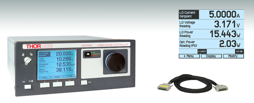
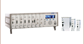
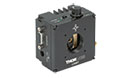
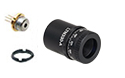
LDC4020
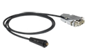
CAB4006


Please Wait
| Item # | LDC4005 | LDC4020 |
|---|---|---|
| Laser Current Control Range | 0 to 5 A | 0 to 20 A |
| Compliance Voltage | 12 V | 11 V |
| Photocurrent Measurement Ranges | 2 mA / 20 mA | |
| Power Monitor Voltage Measurement Ranges |
10 mV / 100 mV / 1 V / 10 V | |
| QCW* Pulse Width Range | 100 µs to 1 s | |
| QCW* Repetition Rate Range | 1 ms to 5 s (0.2 to 1000 Hz) | |
| Internal Modulation Waveforms | Sine, Square, Triangle | |
| Internal Modulation Small Signal Bandwidth |
20 Hz to 100 kHz |
20 Hz to 50 kHz |
*Quasi-Continuous Wave
Laser Diode Controller Features
- Two Models for 5 A and 20 A Laser Currents
- Operate with Anode- or Cathode-Grounded
Laser Diodes and Photodiodes - Also Capable of Driving LEDs in CW
- Continuous Wave or Quasi-Continuous Wave Operation
- Internal Function Generator for Analog Modulation
- External Modulation Input
- Analog Monitor Output for the Laser Current
- Laser Diode Voltage Measurement
- Power Efficient by Active Power Management
- Compatible Optical Detectors:
- Photodiodes
- Thermopiles
- Sensors with Amplifier
- Power Meters
- Control Modes:
- Constant Current (CC)
- Constant Power (CP)
- Enhanced Laser Diode Protection Features:
- Adjustable Laser Current Limit
- Adjustable Laser Power Limit
- Laser Over-Voltage Protection
- Over Temperature Protection
- Interface and Drivers:
- USB Interface (SCPI compliant)
- VXIpnp/VISA Drivers for all Common Programming Environments like LabWindows/CVI™, LabVIEW™, and MS Visual Studio™
The LDC4000 Series of Laser Diode Current Controllers provide precise and stable current for driving high-power laser diodes with injection currents up to 20 A. This series supports all laser diode and monitor diode pin configurations and features a constant current or constant power mode. The series is designed for stand-alone operation and is controlled via front panel keys and intuitive operation menus on a large and easy-to-read graphic LC display. See the Display Screens tab for some examples. Additionally, the LDC4000 Series can be fully remote controlled via an SCPI compatible USB Interface. A higher setting resolution and measurement resolution is offered via remote control.
Compared to the LDC200C Series, the LDC4000 Series offers higher injection currents as well as additional features like the Quasi-Continuous Wave (QCW) operation mode, an internal modulation generator, a thermopile input, laser voltage measurement, and an optical power limit. These features, together with the new design, which offers silent and efficient operation, make the LDC4000 Series Laser Diode Controllers an ideal choice for most applications. Thorlabs recommends recalibrating these controllers every 24 months and offers a factory recalibration service. To order this service, scroll to the bottom of the page and select Item # CAL-LDC4.
For more information about the constant current and constant power modes, the photodiode and thermopile monitor inputs, the continuous wave (CW) or quasi-continuous wave (QCW) operation and the enhanced protection features for the laser diodes please see the More Info tab.
For driver software, as well as programming reference guides for Standard Commands for the Programmable Instruments (SCPI) standard, LabVIEW™, Visual C++, Visual C#, and Visual Basic, please see the Software tab.
Companion Products
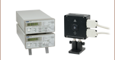
The TED4015 TEC Controller is the ideal companion for the LDC4000 Series Controllers. When combined with our TEC laser mounts, the TED4015 can achieve a thermal stability of 0.001 °C. This temperature stability is required for applications like diode laser wavelength tuning and atomic absorption cell spectroscopy.
| Laser Diode Accessory Selection Guide | |||||
|---|---|---|---|---|---|
| Temperature Controlled Mounts | Passive Mounts | Passive Mounts with Collimation Package | Strain Relief Cables | Diode Sockets | Other Controllers |
 |
 |
 |
 |
 |
 |
Constant Current and Constant Power Modes
The laser diodes can be driven in either constant current (CC) or constant power (CP) mode. In CC mode, the laser current is held precisely at the level set by the user. The CC mode is ideal when the lowest noise and highest response speed is required. In CP mode, the monitoring optical sensor is used to actively stabilize the output power of the laser. A feedback circuit controls the output power of the laser. A power limit can be set to restrict the control loop to a maximum laser output power. To ensure best possible performance, laser diodes are driven with respect to ground, offering significant advantages regarding noise, transient suppression, and stability.
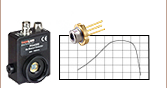
100 µs Pulses of 20 A
Figure: Oscilloscope screenshot of a typ. short 100 µs Pulse of 20.0 A generated by the LDC4020 in QCW mode
Photodiode and Thermopile Monitor Input
The LDC4000 Series allows the user to select photodiodes or thermopiles as the sensor for monitoring the laser diode power output. For each, a monitor input is provided. The photodiode input provides two ranges: 2 mA or 20 mA maximum current. An adjustable-bias voltage can be applied to the photodiode to improve the linearity. The thermopile input provides four ranges: 10 mV, 100 mV, 1 V, or 10 V maximum voltage. Instead of bare thermopile sensors, sensor amplifiers or power meters with analog voltage output can be connected here as well. Both monitor inputs can be calibrated by a sensor response parameter to directly display the optical power in milliwatts.
Continuous Wave (CW) or Quasi-Continuous Wave (QCW) Operation
The LDC4000 Series can be operated in continuous wave (CW) or quasi-CW (QCW) mode. The LDC4020 is at ease providing sharp and accurate 100 µs pulses of 20 A peak current without any unwanted overshoots. The integrated pulse generator can be triggered internally with an adjustable repetition rate or externally via a BNC jack at the rear of the unit.
Enhanced Protection Features for the Laser Diode
For optimal LD protection, the LDC4000 Series offers a set of enhanced protection features. Independent of operation mode or compliance voltage, a precisely adjustable current limit ensures that the maximum allowed laser current cannot be exceeded. The LDC will return an error signal whenever this pre-set limit is reached by user settings or external modulation. The soft start feature ensures a slow increase of the laser current without voltage peaks after the device is switched on. Voltage peaks on the AC line are effectively suppressed by electrical filters and by careful grounding of the chassis. Even in the case of power line failure, the laser current remains transient-free. When the output is disabled, the laser is additionally protected by an electronic output short circuit. If the connection between current source and laser diode is interrupted, or the laser voltage exceeds the adjustable voltage protection threshold, the laser current is switched off.
| Item # | LDC4005 | LDC4020 | ||
|---|---|---|---|---|
| Front Panela | Remote Controla | Front Panela | Remote Controla | |
| Current Control (Constant Current Mode) | ||||
| Laser Diode Current Range | 0 to 5 A | 0 to 20 A | ||
| Compliance Voltage | 12 V | 11 V | ||
| Setting / Measurement Resolution | 1 mA | 80 µA | 1 mA | 320 µA |
| Accuracy | ±(0.1% + 2 mA) | ±(0.1% + 8 mA) | ||
| Noise and Ripple (10 Hz to 10 MHz, RMS, Typ. without Noise Reduction Filter) |
<250 µA | <10 mA | ||
| Noise and Ripple (10 Hz to 10 MHz, RMS, Typ. with Noise Reduction Filter) |
<50 µA | N/A | ||
| Drift, 24 hours (0-10 Hz, Typical at Constant Ambient Temperature) | <300 µA | <1 mA | ||
| Temperature Coefficient | ≤50 ppm/°C | |||
| Current Limit | ||||
| Setting Range | 5 mA to 5 A | 20 mA to 20 A | ||
| Resolution | 1 mA | 80 µA | 1 mA | 320 µA |
| Accuracy | ±(0.12% + 3 mA) | ±(0.12% + 12 mA) | ||
| Power Monitor Input - Photodiode | ||||
| Photocurrent Measurement Ranges | 0 to 2 mA / 0 to 20 mA | |||
| Photocurrent Measurement Resolution (2 mA Range / 20 mA Range) | 1 µA / 10 µA | 32 nA / 320 nA | 1 µA / 10 µA | 32 nA / 320 nA |
| Photocurrent Accuracy (2 mA Range / 20 mA Range) | ±(0.08% +0.5 µA) / ±(0.08% +5 µA) | |||
| Photodiode Reverse Bias Voltage | 0 to 10 V | |||
| Photodiode Input Impedance | ~0 Ω (Virtual Ground) | |||
| Power Monitor Input - Thermopileb | ||||
| Voltage Measurement Ranges | 0 to 10 mV / 0 to 100 mV / 0 to 1 V / 0 to 10 V | |||
| Voltage Measurement Resolution (for 10 mV / 100 mV / 1V / 10 V Ranges) |
1 µV / 10 µV / 100 µV / 1 mV |
0.16 µV / 1.6 µV / 16 µV / 160 µV |
1 µV / 10 µV / 100 µV / 1 mV |
0.16 µV / 1.6 µV / 16 µV / 160 µV |
| Voltage Measurement Accuracy (for 10 mV / 100 mV / 1V / 10 V Ranges) |
±(0.1% + 10 µV) / ±(0.1% + 100 µV) / ±(0.1% + 1 mV) / ±(0.1% + 5 mV) | |||
| Voltage Input Resistance | 1 MΩ | |||
| Laser Power Control (Constant Power Mode) | ||||
| Photocurrent Control Rangesc | 0 to 2 mA / 0 to 20 mA | |||
| Photocurrent Setting Resolution | 1 µA / 10 µA | 32 nA / 320 nA | 1 µA / 10 µA | 32 nA / 320 nA |
| Thermopile Voltage Control Rangesc | 1 µV to 10 mV / 10 µV to 100 mV / 100 µV to 1V / 1 mV to 10 V | |||
| Thermopile Voltage Setting Resolutionc | 1 µV / 10 µV / 100 µV / 1 mV |
0.16 µV / 1.6 µV / 16 µV / 160 µV |
1 µV / 10 µV / 100 µV / 1 mV |
0.16 µV / 1.6 µV / 16 µV / 160 µV |
| Power Limit (Constant Power Mode) | ||||
| Photocurrent Limit Setting Rangesc | 5 µA to 2 mA / 50 µA to 20 mA | |||
| Photocurrent Limit Resolution | 1 µA / 10 µA | 128 nA / 1.28 µA | 1 µA / 10 µA | 128 nA / 1.28 µA |
| Photocurrent Limit Accuracy | ±20 µA / ±200 µA | |||
| Thermopile Voltage Limit Setting Rangesc | 10 µV to 10 mV / 100 µV to 100 mV / 1 mV to 1V / 10 mV to 10V | |||
| Thermopile Voltage Limit Resolution | 1 µV / 10 µV / 100 µV / 1 mV |
730 nV / 7.3 µV / 73 µV / 730 µV |
1 µV / 10 µV / 100 µV / 1 mV |
730 nV / 7.3 µV / 73 µV / 730 µV |
| Thermopile Voltage Limit Accuracy | ±10 µV / ±100 µV / ±1 mV / ±10 mV | |||
| Laser Voltage Measurement | ||||
| Measurement Principle | 4-Wire | |||
| Measurement Range | 0 to 14 V | |||
| Measurement Resolution | 1 mV | 160 µV | 1 mV | 160 µV |
| Accuracy | ±20 mV | |||
| Laser Overvoltage Protection | ||||
| Setting Range | 1 V to 12 V | 1 V to 11 V | ||
| Resolution | 1 mV | |||
| Accuracy | ±50 mV | |||
| Laser Current Monitor Output | ||||
| Load Resistance | >10 kΩ | |||
| Transmission Coefficient | 2 V/A ±5% | 500 mV/A ±5% | ||
| External Modulation Input | ||||
| Input Impedance | 10 kΩ | |||
| Small Signal 3 dB Bandwidth, CC Mode (without Noise Reduction Filter) | DC to 100 kHz (1 Ω Load) | DC to 50 kHz (0.2 Ω Load) | ||
| Small Signal 3 dB Bandwidth, CC Mode (with Noise Reduction Filter) | DC to 6 kHz (1 Ω Load) | N/A | ||
| Modulation Coefficient, CC Mode | 500 mA/V ± 5% | 2 A/V ± 5% | ||
| Modulation Coefficient, CP Mode, Current Sensorc | 200 µA/V / 2 mA/V ±5% | |||
| Modulation Coefficient, CP Mode, Voltage Sensorc | 10 mV/V / 10 mV/V 100 mV/V / 1V/V ±5% | |||
| Internal Modulation | ||||
| Waveforms | Sine, Square, Triangle | |||
| Frequency Range | 20 Hz to 100 kHz | 20 Hz to 50 kHz | ||
| Modulation Depth | 0.1 to 100% | |||
| QCW Mode | ||||
| Pulse Width Range | 100 µs to 1 s | |||
| Pulse Width Resolution | 1 µs | |||
| Repetition Rate Range | 1 ms to 5 s (0.2 to 1000 Hz) | |||
| Repetition Rate Resolution | 10 µs | |||
| Trigger | ||||
| Input | Rising Edge Triggered, Starts QCW Pulse with Internal Adjusted Width | |||
| Input Level | TTL or 5 V CMOS | |||
| Output | Active High, Tracks Pulse Width | |||
| Output Level | TTL or 5 V CMOS | |||
| Dead Time to Next Pulse | >10 µs | |||
| Digital I/O Port | ||||
| Number of I/O Lines | 4 (Separately Configurable) | |||
| Input Level | TTL or CMOS, Voltage Tolerant up to 24 V | |||
| Output Level (Source Operation) | TTL or 5 V CMOS, 2 mA MAX. | |||
| Output Level (Sink Operation) | Open Collector, up to 24 V, 400 mA MAX. | |||
| Interface | ||||
| USB 2.0 | According to USBTMC/USBTMC-USB488 Specification Rev. 1.0 | |||
| Protocol | SCPI Compliant Command Set | |||
| Drivers | VISA VXIpnp™, MS Visual Studio™, MS Visual Studio.net™, NI LabView™, NI LabWindows/CVI™ | |||
| General Data | ||||
| Safety Features | Interlock, Inhibit, Keylock Switch, Laser Current Limit, Laser Power Limit, Soft Start, Short Circuit when Laser off, Adjustable Laser Overvoltage Protection, Over Temperature Protection Temperature Window Protection (only in combination with TED4015) |
|||
| Display | LCD 320 x 240 Pixel | |||
| Connector for Laser, Photodiode, Interlock and Laser On Signal |
13W3 Mixed D-Sub Jack (Female) | |||
| Connectors for Control Input / Output | BNC | |||
| Connector for Digital I/O | Mini DIN 6 | |||
| Connector for USB-Interface | USB Type B | |||
| Chassis Ground Connector | 4 mm Banana Jack | |||
| Line Voltage / Frequency | 100 to 120 V and 200 to 240 V ±10%, 50 to 60 Hz | |||
| Maximum Power Consumption | 200 VA | 600 VA | ||
| Mains Supply Overvoltage | Category II (Cat II) | |||
| Operating Temperature | 0 to 40°C | |||
| Storage Temperature | -40 to 70°C | |||
| Relative Humidity | Max. 80% Up to 31 °C, Decreasing to 50% at 40 °C | |||
| Pollution Degree (Indoor Use Only) | 2 | |||
| Operation Altitude | <2000 m | |||
| Warm-up Time for Rated Accuracy | 20 min | |||
| Weight | 5.5 kg | |||
| Dimensions without Operating Elements (W x H x D) | 263 mm x 122 mm x 307 mm (10.4" x 4.8" x 12.1") | |||
| Dimensions with Operating Elements (W x H x D) | 263 mm x 122 mm x 345 mm (10.4" x 4.8" x 13.6") | |||
All technical data valid at 23 ± 5°C and 45 ±15% relative humidity. Subject to change without notice.
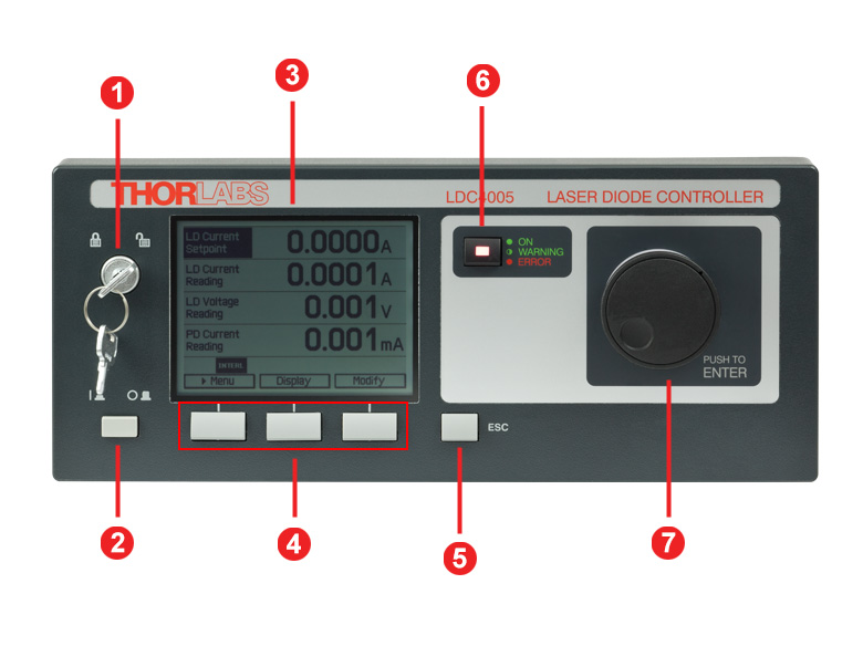
LDC Front Panel
| Callout | Connection | Callout | Connection |
|---|---|---|---|
| 1 | Key Switch | 5 | Escape Key |
| 2 | Supply Power Switch | 6 | LD Status Indicator |
| 3 | LC Display | 7 | Adjustment Knob |
| 4 | Softkeys for Menu Navigation |
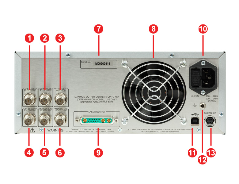
LDC Back Panel
| Callout | Connection | Callout | Connection |
|---|---|---|---|
| 1 | TTL Input "Laser Enable In" 5 V Max | 8 | Cooling Fan |
| 2 | TTL Input "QCW Pulse In" 5 V Max | 9 | LD Output and Optical Sensor Input "Laser Output" |
| 3 | TTL Output "Trigger Out" 0 - 5 V | 10 | Power Connector and Fuse Holder "Line In" |
| 4 | Optical Sensor Input "Opt Sensor In" 0 - 10 V Max |
||
| 5 | Modulation Input "Modulation In" -10 to 10 V |
11 | USB Connector |
| 6 | Laser Current Monitor "Analog CTL Out" 0 - 10 V |
12 | 4 mm Banana Jack for Chassis Ground |
| 7 | Serial Number of the Unit | 13 | MiniDin-6 Jack "Digital I/O" |
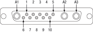
13W3 Mixed D-Sub Jack Pin Configuration
| Pin | Connection | Pin | Connection |
|---|---|---|---|
| 1 | (Thermo) Voltage Sensor Input (+) | 7 | Photo Current Sensor Input (+) |
| 2 | (Thermo) Voltage Sensor Ground (-) | 8 | Photo Current Sensor Ground (-) |
| 3 | Not Connected | 9 | Not Connected |
| 4 | Laser Diode Anode (+) | 10 | Laser Diode Cathode (-) |
| 5 | Output for Interlock and Status Indicator “LASER ON/OFF” (+) | A1 | Laser Diode Ground |
| 6 | Ground Pin for Interlock and Status Indicator “LASER ON/OFF” (-) | A2 | Laser Diode Cathode (with Polarity AG) (-) |
| A3 | Laser Diode Anode (with Polarity CG) (+) |
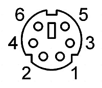
Digital I/O Ports
| Pin | Connection |
|---|---|
| 1 | I/O 1 |
| 2 | I/O 2 |
| 3 | I/O 3 |
| 4 | I/O 4 |
| 5 | GND |
| 6 | I/O Supply Voltage (+12 V from internal or higher external voltage up to +24 V) |
LD Enable In
BNC Female
Laser Enable Input (High to Enable Laser ON), TTL 5 V Max
QCW Pulse In
BNC Female
Input for External Trigger Signal, TTL 5 V Max
Trigger Out
BNC Female
QCW Pulse Tracking Output, TTL 5 V
OPT Sensor In
BNC Female
Input for Optical Sensor, 0 to +10 V Max
Modulation In
BNC Female
Input for External Modulation Signal,
-10 to +10 V Max
Analog CTL Out
BNC Female
Output for Laser Current Monitoring, 0 to +10 V
Computer Connection
USB Type B
USB Type B to Type A Cable Included
Ground
4 mm Banana Jack for Chassis Ground
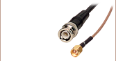
CAB4005 and CAB4006 Laser Diode Cables
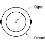
These cables contains a DB-9 male connector on one side and a 13W3 male connector on the other side. Both views shown below are looking into the connector.
DB-9 Male Connector
13W3 Male Connector
| Pin Matching | |
|---|---|
| DB-9 Pin | 13W3 Pin |
| 1 | 5 |
| 2 | 8 |
| 3 | A1 |
| 4 | 7 |
| 5 | 6 |
| 6 | 10 |
| 7 | A2 |
| 8 | A3 |
| 9 | 4 |
| Shield | Shield |
| DB-9 Connector Colors | |
|---|---|
| Pin | Color |
| 1 | White |
| 2 | Gray and Pink |
| 3 | Gray / Black (2 Wires) |
| 4 | Red and Blue |
| 5 | Brown |
| 6 | Blue |
| 7 | Yellow / Purple (2 Wires) |
| 8 | Green / Pink (2 Wires) |
| 9 | Red |
| 13W3 Connector Colors | |||
|---|---|---|---|
| Pin | Color | Pin | Color |
| 1 | No Connection | 9 | No Connection |
| 2 | No Connection | 10 | Blue |
| 3 | No Connection | A1 | Gray / Black (2 Wires) |
| 4 | Red | ||
| 5 | White | A2 | Yellow / Purple (2 Wires) |
| 6 | Brown | ||
| 7 | Red and Blue | A3 | Green / Pink (2 Wires) |
| 8 | Gray and Pink | ||
Sample Screens of the LDC4000 Series
| Measurement Screen | Menu Screen | ||
|---|---|---|---|
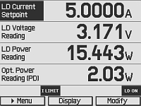 |
The measurement screen offers an easy readout of measurement values and device status information. It also allows to adjust the major instrument setpoints. You can freely select two, four, or six values to be displayed with optimized character size. | 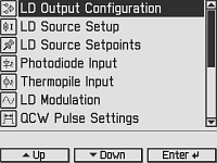 |
The menu screen allows selecting various operation modes and options. |
| Laser Diode Setup Screen | Photodiode Input Screen | ||
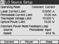 |
The laser diode setup screen allows to enter essential laser control parameters: constant current or constant power mode, limits for laser current and laser power, speed and source of the constant power feedback loop. | 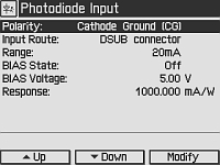 |
Via the photodiode input screen, all parameters concerning the photodiode sensor are entered. |
| QCW Settings Screen | Preferences Screen | ||
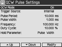 |
This is the input screen for the Quasi-Continous Wave (QCW) pulse mode settings, e.g. trigger source and pulse parameters. | 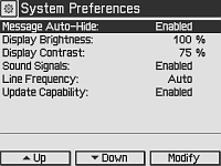 |
The preferences screen offers access to the device preferences, e.g. display and signal settings. |
Software for Laser Diode Controllers
The download button below links to VISA VXI pnp™, MS Visual Studio™, MS Visual Studio.net™, LabVIEW™, and LabWindows/CVI™ drivers, firmware, utilities, and support documentation for Thorlabs' ITC4000 Series laser controllers, LDC4000 Series laser controllers, CLD1000 Series compact laser diode controllers, and TED4000 Series TEC controllers.
The software download page also offers programming reference notes for interfacing with compatible controllers using SCPI, LabVIEW, Visual C++, Visual C#, and Visual Basic. Please see the Programming Reference tab on the software download page for more information and download links.
Driver Software
Version 3.1.0 (April 11, 2014)
Programming Reference
Version 3.3 (April 8, 2015) - SCPI Commands
Version 1.0 (June 16, 2015) - LabVIEW, Visual C++, Visual C#, Visual Basic
The software packages support LabVIEW 8.5 and higher. If you are using an earlier version of LabVIEW, please contact Technical Support for assistance.
LDC4000 Series Shipping List
| Item # | LDC4005 | LDC4020 |
|---|---|---|
| Benchtop Laser Diode Controller, 5 A / 10 V | x | |
| Benchtop Laser Diode Controller, 20 A / 10 V | x | |
| Cable LDC4000/ITC4000 to Laser Mount, 5 A, 13W3, D-Sub-9 (CAB4005) | x | |
| Cable LDC4000/ITC4000 to Laser Mount, 20 A, 13W3, 13W3 (CAB4006) | x | |
| Mixed D-Sub Connector, 13W3, Male & Female with 3 High-Current Contacts Each, 20 A (CON4005) | x | x |
| USB Cable A-B, 2 m | x | x |
| Instrumentation CD Series 4000 | x | x |
| Printed Operation Manual LDC4000 Series | x | x |
| Certificate of Calibration | x | x |
| Posted Comments: | |
进一 严
(posted 2020-11-27 17:32:46.35) I want to control the diode controller from excel. I could reference the TL4000.dll, but it's not a ActiveX component. How to fix this? nreusch
(posted 2020-12-01 10:06:27.0) Thank you for contacting us. I assume you would like to use Visual Basic in Excel. Referencing the Thorlabs TL4000 VXIpnp instrument driver in Visual Basic is the correct approach to successfully implement the driver. Please do so by using an Imports statement as described in the Visual Basic Application note that you can download at https://www.thorlabs.com/software_pages/ViewSoftwarePage.cfm?Code=4000_Series, tab “Programming Reference”. You can then access the functions that are summarized in the HTML manual that you will find on your PC at C:\Program Files (x86)\IVI Foundation\VISA\WinNT\TL4000\manual after having installed the drivers. If you have any questions, please contact your local Tech Support team. Hao Yu
(posted 2020-06-01 00:57:11.14) Your SDK does not support X64 program. Thorlabs.TL4000.dll is a 32 bit dynamic library. MKiess
(posted 2020-06-08 06:59:28.0) This is a response from Michael at Thorlabs. Thank you very much for your inquiry. The 32-bit drivers are installed in a different folder than the 64-bit drivers. The 64-bit version of this instrument driver package installs into your system's VXIpnp directory. This is typically 'C:\Program Files\IVI Foundation\VISA\Win64'. Additional 32-bit libraries install into your 'C:\Program Files (x86)\IVI Foundation\VISA\WinNT'. I have contacted you directly to provide further support. sharrell
(posted 2012-03-06 09:58:00.0) A Response from Sean at Thorlabs: Thank you for your feedback! The ITC current / temperature controllers are essentially a combination of an LDC4000 controller and the TED4015 temperature controller. For example, the ITC4005 will have the same controller specifications as the LDC4005. There is more we can do to simplify the process of selecting the right controller, and we will start by adding a selection guide to our current controller pages, which will list key specifications for our entire current controller line. If you require any further assistance selecting a controller, feel free to email techsupport@thorlabs.com and an applications engineer will be happy to help. user
(posted 2012-03-05 14:26:52.0) I'm picking out current and temperature controllers. It's nice that you have the two ITC specs side by side for comparison, but it would be nice if you also had the specs of the LDC line here for quick comparison. jjurado
(posted 2011-02-16 14:09:00.0) Response from Javier at Thorlabs to zylv: Thank you for contacting us with your request. The LDC4020 shorts the pin A1 A2 and A3 when the laser diode current is not switched on. The shorting of those pins is required in order to ensure that the laser diode has a zero potential difference between its pins, when it is not in use. The fact that you cannot source any current with the driver might be related to a connection problem between the laser diode and the LDC or simply that the polarity is not set properly. We would be happy to help you further with the troubleshooting. I will follow up with you directly. zylv
(posted 2011-02-16 14:02:48.0) LDC4020 could not output the current, I found the Pin A1 A2 and A3 were connected together. could you tell me how fix this issue? This product was dilivered to me yesterday. It is totally new. Thorlabs
(posted 2011-01-19 10:23:34.0) Response from Javier at Thorlabs to aoceron: Thank you very much for submitting your inquiry. The LDC4020 laser diode current controller is designed for benchtop use. We currently do not offer a rack mounting kit for this unit. We do provide, however, 19" rack mounting kits for our PRO8000 chassis, which is designed to hold laser diode test and experimentation modules: http://www.thorlabs.com/NewGroupPage9.cfm?ObjectGroup_ID=895&pn=PRO8000 aoceron
(posted 2011-01-18 22:23:41.0) I was told to use the RK4101 rack-mount kit for the LDC4020, but this wont hold it fix to a 19" rack. Do you have a rack-mount for the LDC4020? or do you have an LDC4020 that is rack-mountable into a 19" rack? Thank you. |
Laser Diode Controller Selection Guide
The tables below are designed to give a quick overview of the key specifications for our laser diode controllers and dual diode/temperature controllers. For more details and specifications, or to order a specific item, click on the appropriate item number below.
| Current Controllers | ||||||
|---|---|---|---|---|---|---|
| Item # | Drive Current | Compliance Voltage | Constant Current | Constant Power | Modulation | Package |
| LDC200CV | 20 mA | 6 V | External | Benchtop | ||
| VLDC002 | 25 mA | 5 V | - | Int/Ext | OEM | |
| LDC201CU | 100 mA | 5 V | External | Benchtop | ||
| LD2000R | 100 mA | 3.5 V | - | External | OEM | |
| EK2000 | 100 mA | 3.5 V | - | External | OEM | |
| LDC202C | 200 mA | 10 V | External | Benchtop | ||
| KLD101 | 230 mA | ≤10 V | External | K-Cube™ | ||
| IP250-BV | 250 mA | 8 Va | External | OEM | ||
| LD1100 | 250 mA | 6.5 Va | - | -- | OEM | |
| LD1101 | 250 mA | 6.5 Va | - | -- | OEM | |
| EK1101 | 250 mA | 6.5 Va | - | -- | OEM | |
| EK1102 | 250 mA | 6.5 Va | - | -- | OEM | |
| LD1255R | 250 mA | 3.3 V | - | External | OEM | |
| LDC205C | 500 mA | 10 V | External | Benchtop | ||
| IP500 | 500 mA | 3 V | External | OEM | ||
| LDC210C | 1 A | 10 V | External | Benchtop | ||
| LDC220C | 2 A | 4 V | External | Benchtop | ||
| LD3000R | 2.5 A | -- | - | External | OEM | |
| LDC240C | 4 A | 5 V | External | Benchtop | ||
| LDC4005 | 5 A | 12 V | Int/Ext | Benchtop | ||
| LDC4020 | 20 A | 11 V | Int/Ext | Benchtop | ||
| Dual Temperature and Current Controllers | |||||||
|---|---|---|---|---|---|---|---|
| Item # | Drive Current | Compliance Voltage | TEC Power (Max) | Constant Current | Constant Power | Modulation | Package |
| VITC002 | 25 mA | 5 V | >2 W | - | Int/Ext | OEM | |
| ITC102 | 200 mA | >4 V | 12 W | Ext | OEM | ||
| ITC110 | 1 A | >4 V | 12 W | Ext | OEM | ||
| ITC4001 | 1 A | 11 V | >96 W | Int/Ext | Benchtop | ||
| CLD1010LPa | 1.0 A | >8 V | >14.1 W | Ext | Benchtop | ||
| CLD1011LPb | 1.0 A | >8 V | >14.1 W | Ext | Benchtop | ||
| CLD1015c | 1.5 A | >4 V | >14.1 W | Ext | Benchtop | ||
| ITC4002QCLd | 2 A | 17 V | >225 W | Int/Ext | Benchtop | ||
| ITC133 | 3 A | >4 V | 18 W | Ext | OEM | ||
| ITC4005 | 5 A | 12 V | >225 W | Int/Ext | Benchtop | ||
| ITC4005QCLd | 5 A | 20 V | >225 W | Int/Ext | Benchtop | ||
| ITC4020 | 20 A | 11 V | >225 W | Int/Ext | Benchtop | ||
We also offer a variety of OEM and rack-mounted laser diode current & temperature controllers (OEM Modules, PRO8 Current Control Rack Modules, and PRO8 Current and Temperature Control Rack Modules).
| Item # | CAB4005 | CAB4006 | CON4005 |
|---|---|---|---|
| Click Image to Enlarge | 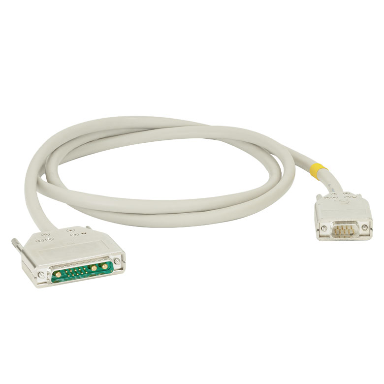 | 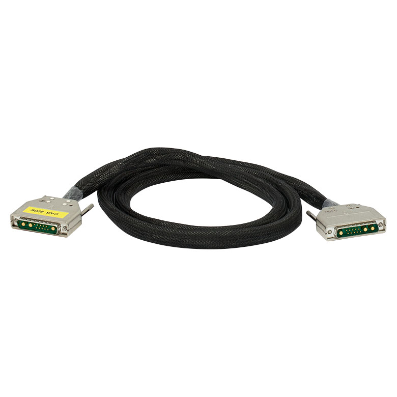 | 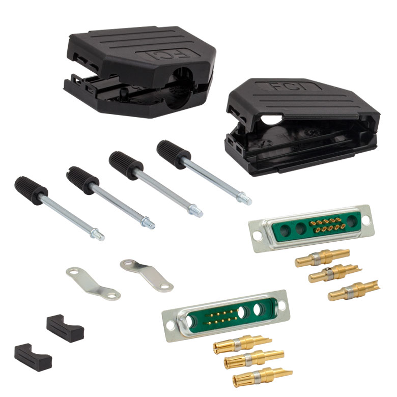 |
| Description | Standard Laser Diode Cable | High Current Laser Diode Cable | 13W3 Male and Female Connector Kit (One Each) |
| Max Current | 5 A | 20 A | 20 A |
| Connector Type | 13W3 Male to DB-9 Male | 13W3 Male to 13W3 Male | Loose 13W3 Connectors, Male and Female |
These cables connect our LDC4000 series current controllers or our ITC4000 series dual current / temperature controllers to laser diodes. We also provide loose 13W3 connectors for customers who wish to make their own cables. For the pinout of the CAB4005 and CAB4006 cables, please see the Pin Diagrams tab.
Please note that one CAB4005 cable and one CON4005 connector kit are included with the purchase of an LDC4005 benchtop controller. The LDC4020 is shipped with the CAB4006 cable and CON4005 connector kit.
| Calibration Service Item # | Compatible Controllers |
|---|---|
| CAL-LDC4 | LDC4005, LDC4020 |
Thorlabs offers a recalibration service for our LDC4000 Series High-Power Laser Diode Controllers. To ensure accurate measurements, we recommend recalibrating the devices every 24 months. The table to the right lists the controllers for which the CAL-LDC4 recalibration service is available.
Requesting a Calibration
Thorlabs provides two options for requesting a calibration:
- Complete the Returns Material Authorization (RMA) form. When completing the RMA form, please enter your name, contact information, the Part #, and the Serial # of the item being returned for calibration; in the Reason for Return field, select "I would like an item to be calibrated." All other fields are optional. Once the form has been submitted, a member of our RMA team will reach out to provide an RMA Number, return instructions, and to verify billing and payment information.
- Enter the Part # and Serial # of the item that requires recalbration below and then Add to Cart. A member of our RMA team will reach out to coordinate return of the item for calibration. Should you have other items in your cart, note that the calibration request will be split off from your order for RMA processing.
Please Note: To ensure your item being returned for calibration is routed appropriately once it arrives at our facility, please do not ship it prior to being provided an RMA Number and return instructions by a member of our team.