 Products Home / Drivers & Mounts / OEM Laser Diode & TEC Systems / OEM 3W Laser Diode Temperature Control
OEM 3W Laser Diode Temperature Control
- High Precision Temperature Control
- Provides 3 W of Power, Current Limited to 1 A
- Interface Cables Included
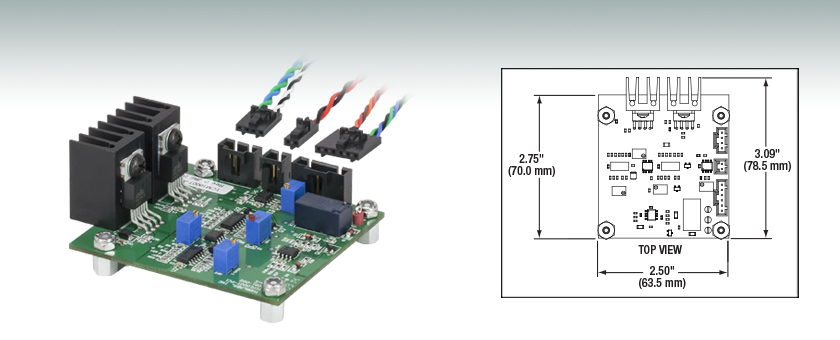
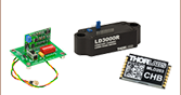
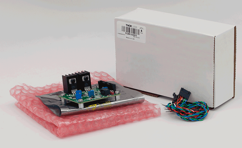
TCM1000T
Includes Connector Wires


Please Wait

| TEC Current Range | Max Output Power | Compliance Voltage |
Input Power | Stability |
|---|---|---|---|---|
| -1 A to 1 A | 3 W | >3 V | +5 VDCa | ±0.1 °Cb |
Features
- High Precision Temperature Control
- Provides 3 W of Power, Current Limited to 1 A
- Interface Cables Included
- OEM Plug-in Version Available
The TCM1000T TEC Controller Module regulates current through a Thermal Electric Cooler (TEC), maintaining a constant temperature of a device; typically a laser diode mounted on the cold-plate. The TCM1000T is a PI controller, for details please see the PID Tutorial tab.
| Control Type | Kp | Ki |
|---|---|---|
| PI | 0.45 Ku | 1.2 Kp/Pu |
Thorlabs' TCM1000T Temperature Controller provides precise temperature control with up to 3 W of cooling power. This OEM style controller features fully adjustable PI settings to maximize its performance when regulating specific devices. Setting the gain levels for the proportional and integral gains to the proper levels will ensure a fast response and stable regulation. The simplest method for setting the gains at proper levels is to use the Ziegler-Nichols method for PID tuning. Start by setting the integral gain to zero; then increase the proportional gain until the circuit starts to oscillate; this gain level is referred to as Ku. The oscillation will have a period of Pu. The gain for the PI circuit is given in the chart to the right (see the PID Tutorial Tab for more information).
Thorlabs also offers OEM TEC Controllers in compact SMT packages.
Jumper Connections

JP1 (Shown in Green)
| Input | Wire Color | Description |
|---|---|---|
| JP1-1 | Green | TEC (+) |
| JP1-2 | Blue | TEC (-) |
| JP1-3 | White | Thermistor In |
| JP1-4 | Black | Thermistor Out (Common) |
JP2 (Shown in Red)
| Input | Wire Color | Description |
|---|---|---|
| JP2-1 | Red | +5 V Power |
| JP2-2 | Black | +5 V Return (Common) |
JP3 (Shown in Blue)
| Input | Wire Color | Description |
|---|---|---|
| JP3-1 | Brown | Relay1 N.O. |
| JP3-2 | Red | Relay1 COM |
| JP3-3 | Orange | Relay1 N.C. |
| JP3-4 | Black | Monitor Ground |
| JP3-5 | Green | Monitor TSET |
| JP3-6 | Blue | Monitor TACT |
PID Basics
The PID circuit is often utilized as a control loop feedback controller and is very commonly used for many forms of servo circuits. The letters making up the acronym PID correspond to Proportional (P), Integral (I), and Derivative (D), which represents the three control settings of a PID circuit. The purpose of any servo circuit is to hold the system at a predetermined value (set point) for long periods of time. The PID circuit actively controls the system so as to hold it at the set point by generating an error signal that is essentially the difference between the set point and the current value. The three controls relate to the time-dependent error signal; at its simplest, this can be thought of as follows: Proportional is dependent upon the present error, Integral is dependent upon the accumulation of past error, and Derivative is the prediction of future error. The results of each of the controls are then fed into a weighted sum, which then adjusts the output of the circuit, u(t). This output is fed into a control device, its value is fed back into the circuit, and the process is allowed to actively stabilize the circuit’s output to reach and hold at the set point value. The block diagram below illustrates very simply the action of a PID circuit. One or more of the controls can be utilized in any servo circuit depending on system demand and requirement (i.e., P, I, PI, PD, or PID).
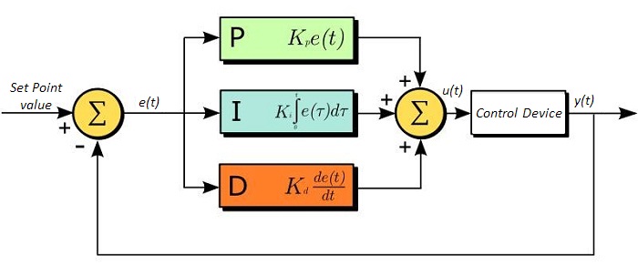
Through proper setting of the controls in a PID circuit, relatively quick response with minimal overshoot (passing the set point value) and ringing (oscillation about the set point value) can be achieved. Let’s take as an example a temperature servo, such as that for temperature stabilization of a laser diode. The PID circuit will ultimately servo the current to a Thermo Electric Cooler (TEC) (often times through control of the gate voltage on an FET). Under this example, the current is referred to as the Manipulated Variable (MV). A thermistor is used to monitor the temperature of the laser diode, and the voltage over the thermistor is used as the Process Variable (PV). The Set Point (SP) voltage is set to correspond to the desired temperature. The error signal, e(t), is then just the difference between the SP and PV. A PID controller will generate the error signal and then change the MV to reach the desired result. If, for instance, e(t) states that the laser diode is too hot, the circuit will allow more current to flow through the TEC (proportional control). Since proportional control is proportional to e(t), it may not cool the laser diode quickly enough. In that event, the circuit will further increase the amount of current through the TEC (integral control) by looking at the previous errors and adjusting the output in order to reach the desired value. As the SP is reached [e(t) approaches zero], the circuit will decrease the current through the TEC in anticipation of reaching the SP (derivative control).
Please note that a PID circuit will not guarantee optimal control. Improper setting of the PID controls can cause the circuit to oscillate significantly and lead to instability in control. It is up to the user to properly adjust the PID gains to ensure proper performance.
PID Theory
The output of the PID control circuit, u(t), is given as
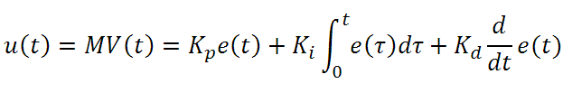
where
Kp= Proportional Gain
Ki = Integral Gain
Kd = Derivative Gain
e(t) = SP - PV(t)
From here we can define the control units through their mathematical definition and discuss each in a little more detail. Proportional control is proportional to the error signal; as such, it is a direct response to the error signal generated by the circuit:
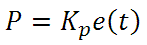
Larger proportional gain results is larger changes in response to the error, and thus affects the speed at which the controller can respond to changes in the system. While a high proportional gain can cause a circuit to respond swiftly, too high a value can cause oscillations about the SP value. Too low a value and the circuit cannot efficiently respond to changes in the system.
Integral control goes a step further than proportional gain, as it is proportional to not just the magnitude of the error signal but also the duration of the error.
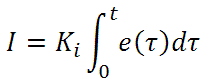
Integral control is highly effective at increasing the response time of a circuit along with eliminating the steady-state error associated with purely proportional control. In essence integral control sums over the previous error, which was not corrected, and then multiplies that error by Ki to produce the integral response. Thus, for even small sustained error, a large aggregated integral response can be realized. However, due to the fast response of integral control, high gain values can cause significant overshoot of the SP value and lead to oscillation and instability. Too low and the circuit will be significantly slower in responding to changes in the system.
Derivative control attempts to reduce the overshoot and ringing potential from proportional and integral control. It determines how quickly the circuit is changing over time (by looking at the derivative of the error signal) and multiplies it by Kd to produce the derivative response.

Unlike proportional and integral control, derivative control will slow the response of the circuit. In doing so, it is able to partially compensate for the overshoot as well as damp out any oscillations caused by integral and proportional control. High gain values cause the circuit to respond very slowly and can leave one susceptible to noise and high frequency oscillation (as the circuit becomes too slow to respond quickly). Too low and the circuit is prone to overshooting the SP value. However, in some cases overshooting the SP value by any significant amount must be avoided and thus a higher derivative gain (along with lower proportional gain) can be used. The chart below explains the effects of increasing the gain of any one of the parameters independently.
| Parameter Increased | Rise Time | Overshoot | Settling Time | Steady-State Error | Stability |
|---|---|---|---|---|---|
| Kp | Decrease | Increase | Small Change | Decrease | Degrade |
| Ki | Decrease | Increase | Increase | Decrease Significantly | Degrade |
| Kd | Minor Decrease | Minor Decrease | Minor Decrease | No Effect | Improve (for small Kd) |
Tuning
In general the gains of P, I, and D will need to be adjusted by the user in order to best servo the system. While there is not a static set of rules for what the values should be for any specific system, following the general procedures should help in tuning a circuit to match one’s system and environment. In general a PID circuit will typically overshoot the SP value slightly and then quickly damp out to reach the SP value.
Manual tuning of the gain settings is the simplest method for setting the PID controls. However, this procedure is done actively (the PID controller turned on and properly attached to the system) and requires some amount of experience to fully integrate. To tune your PID controller manually, first the integral and derivative gains are set to zero. Increase the proportional gain until you observe oscillation in the output. Your proportional gain should then be set to roughly half this value. After the proportional gain is set, increase the integral gain until any offset is corrected for on a time scale appropriate for your system. If you increase this gain too much, you will observe significant overshoot of the SP value and instability in the circuit. Once the integral gain is set, the derivative gain can then be increased. Derivative gain will reduce overshoot and damp the system quickly to the SP value. If you increase the derivative gain too much, you will see large overshoot (due to the circuit being too slow to respond). By playing with the gain settings, you can maximize the performance of your PID circuit, resulting in a circuit that quickly responds to changes in the system and effectively damps out oscillation about the SP value.
| Control Type | Kp | Ki | Kd |
|---|---|---|---|
| P | 0.50 Ku | - | - |
| PI | 0.45 Ku | 1.2 Kp/Pu | - |
| PID | 0.60 Ku | 2 Kp/Pu | KpPu/8 |
While manual tuning can be very effective at setting a PID circuit for your specific system, it does require some amount of experience and understanding of PID circuits and response. The Ziegler-Nichols method for PID tuning offers a bit more structured guide to setting PID values. Again, you’ll want to set the integral and derivative gain to zero. Increase the proportional gain until the circuit starts to oscillate. We will call this gain level Ku. The oscillation will have a period of Pu. Gains are for various control circuits are then given below in the chart.
Click to Enlarge
Updated TCM1000T Packaging

Smart Pack Goals
- Reduce Weight of Packaging
- Increase Usage of Recyclable Materials
- Improve Packing Integrity
- Decrease Shipping Costs
Thorlabs' Smart Pack Initiative is aimed at minimizing waste while providing adequate protection for our products. By eliminating any unnecessary packaging, implementing design changes, and utilizing eco-friendly materials, this initiative seeks to reduce the environmental impact of our product packaging.
The updated TCM1000T packaging consists of recycled plastic bubble wrap and cardboard and weighs 19% less than the original packaging. This weight change results in a 3.72 kg reduction in travel-based CO2 emissions per year, based on typical product sales.
As we move through our product line, we will indicate re-engineered, eco-friendly packaging with our Smart Pack logo, which can be seen above.
| Posted Comments: | |
Ali Ali
(posted 2019-08-27 20:40:48.783) i am interested to use IP250-BV laser diode drivers from thorlabs as a OEM driver to operate my laser diode. However, IP250-BV do not offer any cooling capabilities. For temperature controller, could i used TCM1000T as a temperature controller? YLohia
(posted 2019-08-27 08:42:00.0) Hello, thank you for contacting Thorlabs. The TCM1000T is designed to provide TEC control for laser diodes. That being said, you must ensure that you laser diode heat load does not exceed 3 Watts as this is the maximum cooling capacity of this controller. Please also note that the maximum TEC current is limited to 1 A. massimo.fedel
(posted 2013-12-03 10:17:14.34) Dear Sir/Madam, I would like to order your TCM1000T and I need a technical information.
I want to use TCM1000T with a laser with integrated Thermistore resistance (10kohm) and integrated tec with max forward current 0,7A, and Max forward voltage 2,5V.
I want to reach Tset very slowly:
What is the best PID setting?
I don't want to damage the laser,what can I do to limit the voltage(2,5Vmax) and the current (0,7Amax)?
Thanks in advance for any help,
Regards,
Massimo jlow
(posted 2013-12-17 01:58:59.0) Response from Jeremy at Thorlabs: There's no way to limit the output current and voltage on the TCM1000T to a user-selected setting. With regard to reaching Tset very slowly, in theory you can reduce the P-gain to be very low, but you still have to deal with the I-gain opamp which can saturate at 5V. We also offer the TED200C or TCH001 which has an option to set your own current limit. bdada
(posted 2012-04-26 18:56:00.0) Response from Buki at Thorlabs to toptygin:
Thank you for your feedback. We have sent you the schematic and are already taking steps to improve the information provided in the manual and on our website. toptygin
(posted 2012-04-24 16:33:57.0) I have purchased two TCM1000T controllers from Thorlabs on October 25, 2011. The system for which the controllers were purchased is now complete, and I am trying to optimize its transient behavior. I have read the "Operating Manual" a dozen times by now, but I still cannot figure out what is the function of the trimpots PGAIN and IGAIN. If I had a schematic diagram, then it would take me 30 seconds to understand the exact functions of these trimpots, however, Thorlabs did not include a schematic diagram with the manual. I can reverse-engineer the controller and draw its schematic diagram, but this would take a couple of days. Could you please find the schematic diagram and send it to my email address toptygin@jhu.edu ? klee
(posted 2009-10-05 10:43:30.0) A response from Ken at Thorlabs to pierre.devillers: The TCM1000T is ROHS Exempt. You can get the certificate by clicking on the Documents & Drawings tab, and then click on the ROHS Exempt icon. pierre.devillers
(posted 2009-10-02 14:39:43.0) Is the 3W TEC Controller TCM1000T ROHS compliant ? If yes, is it possible to get its compliance certificate ?
Thanks,
Pierre de Villers klee
(posted 2009-09-24 15:15:26.0) A response from Ken at Thorlabs to jian.chu: Currently we do not have a 3D model for this product. I am checking with our engineering group to see if they can make one for you. I will let you know by email. jian.chu
(posted 2009-09-24 09:40:40.0) Dear Sir/Madam,
Could you please send us 3D model(in igs or stp format) of board TCM1000T?
We need it to import to our assembly model.
Thank you very much.
Thanks
Jian Chu
-----------------------------------
MPB Telecommunication
Engineering Dept
Tel: 514-694-8751 ext.306
jian.chu@mpbc.ca
www.mpbc.ca |