 Products Home
OEM VCSEL Diode Drivers
- For VCSEL Diodes
- Designed to Supply Low Drive Current
- Enhanced Safe Operation of VCSEL Diodes
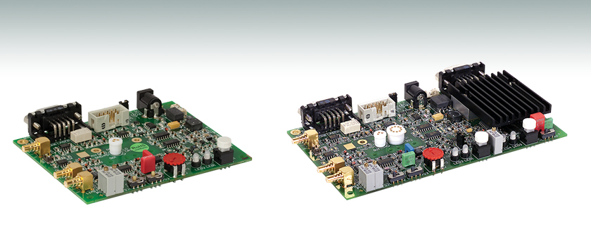
VLDC002
VITC002


Please Wait
Features
- Constant Current Operation
- Modulation Input
- Internal Triangular Modulation for Sweep Application
- Low Noise Output Stage
- Analog Control Outputs for Laser Current, Laser Current Limit, Monitor Photodiode Current
- Laser Temperature Control with Standard Thermistor (VITC002 only)
- Analog Control Outputs for Set and Actual Thermistor Resistance (VITC002 only)
- Two Available Versions:
- VLDC002: OEM VCSEL Driver without Temperature Controller, TO-46 Socket on Board
- VITC002: OEM VCSEL Driver with Temperature Controller, TO-46 and TO-5 Socket on Board
The VLDC002 and VITC002 are compact and easy to use laser current controllers for VCSEL Diodes (Vertical Cavity Surface Emitting Laser). These controllers are designed to supply the low drive current typical for a VCSEL. They are well suited for OEM application as well as for flexible setups in the lab. A universal 5V DC power supply is included.
Functionality
These drivers have an onboard TO-Type Socket into which the VCSEL diodes can be directly plugged. An integrated triangular current modulation feature allows high speed sweeping of the wavelength of the VCSEL for spectroscopy applications. Alternatively, an analog input enables external wavelength modulation. An adjustable modulation current upper limit protects the laser diode from accidental damage when using either of these features.
Safe VCSEL Operation
A variety of safety measures allows easy and safe operation of VCSEL up to 25mA. Special attention has been paid to ensuring an extremely clean low noise drive current to prevent damage to the highly sensitive VCSEL Diodes. A temperature window indicator LED shows when the diode leaves a desired operation temperature range, thus providing an indication that an unwanted wavelength shift may have occurred (VITC002 only). An open circuit output detection, and an interlock which prevents damage from bad contacts enhance the safe operation of the sensitive VCSEL diodes.
| Special Note: Please determine the polarity of the VCSEL being driven. The polarity of the VCSEL Laser Current Source is fixed in the AG (anode grounded) arrangement and cannot be changed. These drivers can operate only pin compatible VCSEL lasers. The VLDC002 is designed for the VCL Laser Series, while VITC002 is suited for both the VCL and VCT laser series. For more information, please see the VLDC002 or VITC002 operating manuals or contact tech support. |
| Specification for VLDC002 and VITC002 | |
|---|---|
| Current Control | |
| Laser Diode Polarity | Anode Grounded (AG), Fixed |
| Current Range | 0 - 25 mA |
| Compliance Voltage | >5 V |
| Noise | <0.8 µA Typical |
| Drift (24 hours at Constant Ambient Temperature) | <5 µA |
| Temperature Coefficient | ≤± 50 ppm/°C |
| Current Limit | 0 - 25 mA |
| Internal Triangular Modulation | |
| Frequency Range | 1 Hz - 10 kHz |
| Amplitude | 0 - 25 mA |
| Modulation Depth | 90% Typical |
| Balance Rise / Fall | 50% Typical |
| Analog Modulation Input | |
| Frequency Range (-3 dB) | DC - 100 kHz |
| Input Voltage Range | 0 - 2.5 V |
| Input impedance | 10 kΩ |
| Modulation Coefficient | 10 mA/V ± 5% |
| Photodiode Input | |
| Input Current Range | 0 to ± 2.5 mA |
| Input Impedance | Virtual Ground |
| Control Outputs | |
| Set Laser Current | 0 - 2.5 V |
| Actual Laser Current | 0 - 2.5 V |
| Photodiode Current | 0 to ±2.5 V |
| Minimum Load Resistance for Rated Accuracy | 1 MΩ |
| Accuracy (f.s.) | ±1% |
| Connectors | |
| Laser Socket | 3-pin on 2.54 mm Diameter Circle 10-pin on 5.84 mm Diameter Circle (VITC002 only) |
| Laser / Photodiode / Interlock | D-Sub 9 Pin, Female |
| Modulation Input | SMB |
| PD Input | SMB |
| TEC Element / Thermistor (VITC200 Only) | D-Sub 9 Pin, Male |
| General Data | |
| Power Supply Requirement | 5 VDC ± 5%, Regulated, 350 mA (VLDC002), 1.3 A (VITC002) |
| Included Wall Power Supply | 90 ... 264 VAC / 5 VDC |
| Current Requirement | 350 mA (VLDC002), 1.3 A (VITC002) |
| Operating Temperature | 0 - 40 °C |
| Storage Temperature | -40 - 70 °C |
| Dimensions PCB (W x D) | VLDC002: 80 mm x 100 mm VITC002: 80 mm x 140 mm |
| Dimensions Overall (W x D x H) | VLDC002: 87 mm x 105 mm x 17 mm VITC002: 87 mm x 145 mm x 17 mm |
| Additional Specifications only for VITC002 | |
|---|---|
| Temperature Control | |
| TEC Current | 0 to ±0.2 A / ±0.8 A (Selectable) |
| TEC Voltage | >2.5 V |
| Max. TEC Power | >2 W |
| Noise and Ripple | <1 mA Typical |
| TEC Current Limit | 0.2 A / 0.8 A Typical (Selectable) |
| Temperature Sensor | |
| Thermistor Control Range | 5 to 20 kΩ |
| Accuracy (f.s.) | 2% Typical |
| Stability | 2 Ω |
| Reproducibility | ±0.1% |
| Temperature Window | ±0.5 kΩ Typical |
| Control Outputs | |
| Set Thermistor Resistance | +0.5 to +2.5 V |
| Actual Thermistor Resistance | +0.5 to +2.5 V |
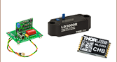
| Included Parts | ||
|---|---|---|
| VLDC002 | VITC002 | Part |
| x | OEM VCSEL Driver with Temp. Controller, TO-46 Socket on Board (VLDC002) | |
| x | OEM VCSEL Driver with Temp. Controller, TO-46 and TO-5 Sockets on Board (VITC002) | |
| x | x | Universal Input Power Supply |
| x | x | Operating Manual |
VLDC002 Top View

CON5 - Analog and TTL Control Outputs

| Pin | Signal | Range |
|---|---|---|
| 1 | GND | - |
| 2 | LD ON | TTL, High when the Output is Switched On |
| 3 | ERROR | TTL, High when an Error Occurs |
| 4 | ILD SET | Set Laser Current, 100 mV/mA |
| 5 | ILD ACT | Actual Laser Current, 100 mV/mA |
| 6 | IPD | Photodiode Current, 1V/mA |
| 7...10 | Not Connected | - |
CON6 - Connector for External Laser Diode
D-type Female
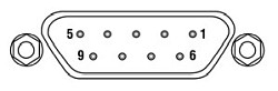
| Pin | Function | Range |
|---|---|---|
| 1 | Interlock / LED "ON" | Needs Low Ohmic Return to Pin 5 |
| 2 | Monitor Diode GND | - |
| 3 | Laser Anode, GND | - |
| 4 | Monitor Diode In | 0 ... 2.5 mA |
| 5 | Interlock / LED GND | - |
| 7 | Laser Cathode | 0 ... 25 mA |
| 6,8,9 | Not Connected | - |
| Shield | GND | - |
SO1 - Laser Diode Socket
2 or 3 Pin Laser Diodes
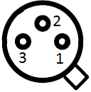
| Pin | Function |
|---|---|
| 1 | Laser Cathode |
| 2 | Laser Anode, GND |
| 3 | Laser Anode, GND |
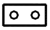
JP1
Interlock

A short-circuit or at least a low resistance (R<300 Ω) must be maintained between pin 1 and pin 5 for laser power to remain "on." It is also possible to use a LED with a 1 kΩ resistor in parallel between the two pins. The LED will light up if the laser current output is switched on.
CON2 - SMB Male
External Set Input for the Laser
Current
CON3 - SMB Male
Modulation Input for the Laser
Current
CON4 - SMB Male
Input for External Photo Diode
VITC002 Top View

CON7 - Connector for External Temperature Control
D-type Female
| Pin | Function | Range |
|---|---|---|
| 2 | Thermistor | 20 µA |
| 3 | Thermistor Ground | - |
| 4 | TEC + | -0.2 ... +0.2 A / -0.8 ... +0.8 A (Selectable) |
| 5 | TEC - | +0.2 ... -0.2 A / +0.8 ... -0.8 A (Selectable) |
| Shield | GND | - |
CON5 - Analog and TTL Control Outputs
| Pin | Signal | Range |
|---|---|---|
| 1 | GND | - |
| 2 | LD ON | TTL, High when the Output is Switched On |
| 3 | ERROR | TTL, High when an Error Occurs |
| 4 | ILD SET | Set Laser Current, 100 mV/mA |
| 5 | ILD ACT | Actual Laser Current, 100 mV/mA |
| 6 | IPD | Photodiode Current, 1 V/mA |
| 7 | R ACT | Actual Thermistor Resistance, 100 mV/kΩ |
| 8 | R SET | Set Thermistor Resistance, 100 mV/kΩ |
| 9 | OUT OF WIN | TTL, High when the Thermistor Resistance is out of the Window |
| 10 | TEC ON |
TTL, High when the Temperature Control is Switched On |
CON6 - Connector for External Laser Diode
D-type Female
| Pin | Function | Range |
|---|---|---|
| 1 | Interlock / LED "ON" | Needs Low Ohmic Return to Pin 5 |
| 2 | Monitor Diode GND | - |
| 3 | Laser Anode, GND | - |
| 4 | Monitor Diode In | 0 ... 2.5 mA |
| 5 | Interlock / LED GND | - |
| 7 | Laser Cathode | 0 ... 25 mA |
| 6,8,9 | Not Connected | - |
| Shield | GND | - |
JP1
Interlock
A short-circuit or at least a low resistance (R<300 Ω) must be maintained between pin 1 and pin 5 for laser power to remain "on." It is also possible to use a LED with a 1 kΩ resistor in parallel between the two pins. The LED will light up if the laser current output is switched on.
JP2
Laser Temperature Window Protection
Pull jumper JP2 to enable the temperature window protection. With the temperature window protection enabled, the laser is switched off (or cannot be switched on) while the actual thermistor resistance is out of the ±0.5 kΩ window. As soon as the actual resistance re-enters the window, the laser is switched on again (or can be switched on again).
SO1 - Laser Diode Socket
2 or 3 Pin Laser Diodes
| Pin | Function |
|---|---|
| 1 | Laser Cathode |
| 2 | Laser Anode, GND |
| 3 | Laser Anode, GND |
CON2 - SMB Male
External Set Input for the Laser Current
S02 - Laser Diode Socket
10 Pin Laser Diodes

| Pin | Function |
|---|---|
| 1 | TEC + |
| 3 | Laser Cathode |
| 4 | Laser Anode, GND |
| 8 | Thermistor GND |
| 9 | Thermistor |
| 10 | TEC - |
| 2,5,6,7 | Not Used |
CON3 - SMB Male
Modulation Input for the Laser Current
CON4 - SMB Male
Input for External Photo Diode
| Posted Comments: | |
Haoran Zhu
(posted 2022-10-21 14:46:40.457) hi
We have an external Laser to connect with the laserdriver(VITC002) in our Lab, and need some technik supports.
1. The Laser should working at the specific temperatur and we can calculate the resistance. the question is we should set the resistance from Laserdriver as temperatur control system. Is that p4 on the board we could direct chance to the calculated resistance? (Manual page 24/ 3.3.5 Adjusting the Thermistor set resistance)
2. as Manual page 21/ 3.3.1 Adjusting the limit. we could adjust ILimit. Is that current as same as ILD? (to ensure that the Laser LD Cathode&Anode is at a safe current.) if not what is the different between this two?
3.same, the current given to the TEC+ and TEC- ports of the Laser, also needs to be given a safe value by the driver (the maximum current of our laser TEC is 0.9A), so what components can the driver control through?
i dont know if you can solve my problem, if positiv answer thanks a lot
Haoran hkarpenko
(posted 2022-10-28 08:03:28.0) Dear Haoran,
thank you very much for your feedback. I contacted you directly to discuss this with you. Tyler
(posted 2008-10-03 09:14:29.0) A response from Tyler at Thorlabs to s.obyrne: After talking to our engineers in Germany I have some additional information. They recommend using Thorlabs benchtop controller (LDC200CV) since it was designed to allow for the operation of diodes with that pin configuration. However, if an OEM type driver is necessary, the only solution is to desolder the socket and rewire it for your pin configuration. This will potentially introduce noise into the system. The more elegant solution of altering the circuit directly is not possible because the circuit board is multilayered. Tyler
(posted 2008-09-25 09:50:11.0) A response from Tyler at Thorlabs to s.obyrne: Unfortunately, it is not reasonable to make changes to the VITC002 circuit to make it compatible with a cathode grounded VCSEL. Thank you for considering Thorlabs for you photonics needs. s.obyrne
(posted 2008-09-25 06:26:06.0) I would like to use this driver with a VCSEL from a company other than vertilas. They produce their diodes with the cathode at ground, and I understand that this circuit uses anode ground. Is there anything I can do with this circuit to allow it to work with a diode whose cathode is connected to the case and the negative TEC input?
Thanks |
Laser Diode Controller Selection Guide
The tables below are designed to give a quick overview of the key specifications for our laser diode controllers and dual diode/temperature controllers. For more details and specifications, or to order a specific item, click on the appropriate item number below.
| Current Controllers | ||||||
|---|---|---|---|---|---|---|
| Item # | Drive Current | Compliance Voltage | Constant Current | Constant Power | Modulation | Package |
| LDC200CV | 20 mA | 6 V | External | Benchtop | ||
| VLDC002 | 25 mA | 5 V | - | Int/Ext | OEM | |
| LDC201CU | 100 mA | 5 V | External | Benchtop | ||
| LD2000R | 100 mA | 3.5 V | - | External | OEM | |
| EK2000 | 100 mA | 3.5 V | - | External | OEM | |
| LDC202C | 200 mA | 10 V | External | Benchtop | ||
| KLD101 | 230 mA | ≤10 V | External | K-Cube™ | ||
| IP250-BV | 250 mA | 8 Va | External | OEM | ||
| LD1100 | 250 mA | 6.5 Va | - | -- | OEM | |
| LD1101 | 250 mA | 6.5 Va | - | -- | OEM | |
| EK1101 | 250 mA | 6.5 Va | - | -- | OEM | |
| EK1102 | 250 mA | 6.5 Va | - | -- | OEM | |
| LD1255R | 250 mA | 3.3 V | - | External | OEM | |
| LDC205C | 500 mA | 10 V | External | Benchtop | ||
| IP500 | 500 mA | 3 V | External | OEM | ||
| LDC210C | 1 A | 10 V | External | Benchtop | ||
| LDC220C | 2 A | 4 V | External | Benchtop | ||
| LD3000R | 2.5 A | -- | - | External | OEM | |
| LDC240C | 4 A | 5 V | External | Benchtop | ||
| LDC4005 | 5 A | 12 V | Int/Ext | Benchtop | ||
| LDC4020 | 20 A | 11 V | Int/Ext | Benchtop | ||
| Dual Temperature and Current Controllers | |||||||
|---|---|---|---|---|---|---|---|
| Item # | Drive Current | Compliance Voltage | TEC Power (Max) | Constant Current | Constant Power | Modulation | Package |
| VITC002 | 25 mA | 5 V | >2 W | - | Int/Ext | OEM | |
| ITC102 | 200 mA | >4 V | 12 W | Ext | OEM | ||
| ITC110 | 1 A | >4 V | 12 W | Ext | OEM | ||
| ITC4001 | 1 A | 11 V | >96 W | Int/Ext | Benchtop | ||
| CLD1010LPa | 1.0 A | >8 V | >14.1 W | Ext | Benchtop | ||
| CLD1011LPb | 1.0 A | >8 V | >14.1 W | Ext | Benchtop | ||
| CLD1015c | 1.5 A | >4 V | >14.1 W | Ext | Benchtop | ||
| ITC4002QCLd | 2 A | 17 V | >225 W | Int/Ext | Benchtop | ||
| ITC133 | 3 A | >4 V | 18 W | Ext | OEM | ||
| ITC4005 | 5 A | 12 V | >225 W | Int/Ext | Benchtop | ||
| ITC4005QCLd | 5 A | 20 V | >225 W | Int/Ext | Benchtop | ||
| ITC4020 | 20 A | 11 V | >225 W | Int/Ext | Benchtop | ||
We also offer a variety of OEM and rack-mounted laser diode current & temperature controllers (OEM Modules, PRO8 Current Control Rack Modules, and PRO8 Current and Temperature Control Rack Modules).